Circuit Card
Nortel Networks Communication Server
Page
September
Revision history
October
4 of 894 Revision history Standard 2.00 September
Contents
Option settings
NT1R20 Off-Premise Station Analog Line card 155
NT5D33 and NT5D34 Lineside E1 Interface cards
NT5K02 Flexible Analog Line card
NT7D16 Data Access card
NT8D03 Analog Line card
NTAG26 Xmfr card
NTAK02 SDI/DCH card
NTAK93 D-channel Handler Interface daughterboard
NTDK20 Small System Controller card
NTVQ55AA ITG Pentium card
Appendix a Lapb Data Link Control Protocol
18 of 894 Contents
About this document
Subject
Applicable systems
Conventions
Intended audience
Terminology
Related information
NTPs
Online
CD-ROM
24 of 894 About this document Standard 2.00 September
Contents
Overview
Line card characteristics
Line cards
NT5D33 and NT5D34 Lineside E1 Interface card
NT1R20 Off-Premise Station Analog Line card
NT5D11 lineside T1 interface card
NT8D02 digital line card
IPE line cards shown installed in an NT8D37 IPE module
Installation
NT8D09 analog message waiting line card
Operation
Host interface bus
IPE module architecture Parameter
Intelligent Peripheral Equipment
IPE
Overview Page 31
32 of 894 Overview Typical IPE analog line card architecture
DS-30X loops
Card LAN link
Analog line interface units
Codec
Balancing network
Coder/Decoder circuit
Variable gain filters
Line interface and foreign voltage protection
Digital line interface units
TCM loop interfaces
Signaling
Overview Page 39 Digital line interface unit block diagram
Incoming calls
Analog line call operation
Outgoing calls
State
State
Message waiting
Analog line supervision
Digital line call operation
Lineside T1 call operation
Signal/direction Remarks
Far-end Station System Line card Near-end
Loop Start Mode
Incoming calls
Outgoing calls
Outgoing Calls
Call Disconnect from far end
Ground Start Mode
Call disconnect from terminal equipment
Overview Page 51
52 of 894 Overview
Ground Start Restrictions
Outgoing Calls from terminal equipment
Distant end disconnect restrictions
Off-premise line protection
Voice frequency audio level
Line protectors
Line protection grounding
6AP
Telephones
Trunk cards
Line and telephone components
Line cards
Trunk Types
Trunk card characteristics Part Number Description
NT8D14 Universal Trunk card
IPE
NT8D15 E&M Trunk card
Installation
NTCK16 Generic Central Office Trunk card
Brsc
Host interface bus
Operation
Differences between IPE parameters Parameter
62 of 894 Overview Typical IPE trunk card architecture
Overview Page 63
64 of 894 Overview
Overview Page 65 DS-30X loop data format
NT8D13 PE Module
DS-30Y
Loop
Large
Trunk interface unit
Typical trunk interface unit block diagram
TS0
Variable gain filters
Serial Data Interface SDI cards
NT8D41BA
Features
Uses
Specifications
Electrostatic discharge
Power consumption
Environmental
NT8D41BA
Electromagnetic interference
Maintenance
Configuring the system software
Reliability
Overview Page 75
76 of 894 Overview
Circuit card installation
Card slots Large System
Circuit card installation
Large System card slots Part 1 Component
Large System card slots Part 2 Component
Large System card slots Part 3 Component
NT6D80 Msdl
Large System card slots Part 4 Component
IPE DLB
Precautions
Static discharge points
Procedure Installation
Installing a circuit card
System Failure
Installing the circuit card in the card cage
Page
Acceptance tests
Introduction
Uneq
Conference cards
Dsbl
Cnfc MAN loop c
Cnfc loop
Cnfc Step
Digitone receiver cards
End of Procedure
Procedure Testing digitone receiver cards
LD 34 Stat
Procedure Testing line cards
Untt l s c
LD 46 MFS loop
Procedure Testing multifrequency sender cards
Multifrequency sender cards
Tone loop ALL
Procedure Testing network cards
Multifrequency signaling cards
Procedure Testing multifrequency signaling cards
Network cards
TRK l s c u
Call or Call l s c u
Procedure Testing tone and digit switch cards
Tone and digit switch cards
LD 34 Stad
TDS loop
LD#34##
Acceptance tests Page 97
98 of 894 Acceptance tests Standard 2.00 September
Option settings
Circuit card grid
Circuit card grid
NT1R20 Off-Premise Station card
ONP OPX
Timp
Bimp
3COM1 3COM2
Trunk interface switches
General purpose switches
NT5D12AA Dual DTI/PRI DDP card
106 of 894 Option settings
Ring ground switches
DCH mode and address select switches
Ddch
Illustrations of switch locations and settings
DDP
Switch default settings
NT6D42 Ringing Generator DC
NT6D42 jumper location J7 Ringing output Jumper location J7
NT6D42CB SW2
NT6D42 SW1 Ringing frequency Hz Position SW1
Ringing Message waiting Voltage
NT6D42CC SW2
NT5D2101/NT9D1102 Core/Network module backplane
NT6D68 Core module backplane
NT6D80 Multi-purpose Serial Data Link card
NT6D80 Multi-purpose Serial Data Link card
NT8D14 Universal Trunk card
CO/FX/WATS
Jumper strap settings J1.X J2.X J3.X J4.X
Did
5000 ft
Way tie Oaid 600 or
Option settings Page 121
Rcv Type Paging
NT8D15 E&M Trunk card
Xmt
Companding law Jumper at J3
NT8D17 Conference/TDS card
SW2 see Note Attenuation levels
Settings Frequency Amplitude
NT8D21 Ringing Generator AC
NT8D22 System Monitor
NT8D22 SW1
SW1 function
CTR
NT8D22 SW2 Position SW2 indication
NT8D22 SW3 Position SW3 indication
Fail
128
129
Address
NT8D41BA Quad Serial Data Interface Paddle Board
Baud rate
KHz
Device
DTE/DCE mode
Pair
NT8D72 Primary Rate Interface card
NT8D72 DIP switch settings
NT8D72BA
Options minimum vintage N
QPC43 Peripheral Signaling card
QPC71 E&M/DX Signaling and Paging Trunk cards
Plug location
Pin connection
QPC414 Network card
Application J3/S2 and J4/S1
QPC441 3-Port Extender cards
QPC441 3PE card installed in the NT5D21 modules
Switch Settings Module D20 switch position
Shelf Group
QPC559, QPC560 Loop Signaling Trunk cards
Jumpers QPC560 Units 0/1/2/3
Jumpers QPC560 Units 0/1/2/3
Lists switch and jumper settings for options available
QPC528 CO/FX/WATS Trunk cards
QPC471 vintage H
QPC471 Clock Controller card
SW1 SW2 SW4
Switches at E29/E9/A29/A11 Units 0/1/2/3
QPC525, QPC526, QPC527, QPC777 CO Trunk card
QPC550 Direct Inward Dial Trunk card
Location Designation Number Pad Pad out
146
Application S3 E2 S4 F2 Unit 0, Unit
Signal duration on the 18-pair faceplate
Signal duration and pause time
S5 E38 S6 D1 Unit
QPC720 Primary Rate Interface card
QPC595 Digitone Receiver cards
QPC577, QPC596 Digitone Receiver daughterboards
Location Connection
Switch 3 option for DTI with ESF
QPC775 Clock Controller card
QPC775 before vintage E switch settings
QPC775 vintage E switch settings
SW2 SW3 SW4
QPC841 4-Port Serial Data Interface card
QPC841 baud rate
Device number SW15 Port
Port 2 SW11 Port 3 SW12 Port 4 SW13 Baud Rate
DTE
QPC841 DTE or DCE selection Mode
DCE
154 of 894 Option settings
NT1R20 Off-Premise Station Analog Line card
Physical description
Self Test
OPS analog line card faceplate
LED
OPS analog line card block diagram
Functional description
Power interface
Voice and signaling interfaces
Maintenance communication
Card interfaces
Line interface units
Signaling and control
Card control functions
Microcontroller
Software service changes
Card LAN interface
ONS OPS
3COM
Circuit power
Electrical specifications
Port-to-port loss configuration
Analog line interface
Foreign and surge voltage protection
Power requirements
Ringer limitations
Environmental specifications
Incoming calls
Outgoing calls
NT1R20 Off-Premise Station Analog Line card
Connector pin assignments
MDF
OPS analog line card typical cross connection example
Configuring the OPS analog line card
Jumper strap settings
Application
Off-premise station application
OPS analog line card jumper block locations
NT1R20 Off-Premise Station Analog Line card Page 175
Traditional OPS application configuration
Coops
Other applications
Transmission considerations
Port-to-port loss
Termination transmission characteristics
180 of 894 NT1R20 Off-Premise Station Analog Line card
NT5D11 and NT5D14 Lineside T1 Interface cards
Card connections
Faceplate
Lineside T1 card faceplate
Card lock latch Card status LED
RED
LED
Status
YEL
NT5D11 and NT5D14 Lineside T1 Interface cards Page 185
Lineside T1 card block diagram
Seq
NT5D11 and NT5D14 Lineside T1 Interface cards Page 187
Signaling and control
T1 interface circuit
Sanity timer
Microcontrollers
T1 channel specifications
Man-Machine Interface
Lineside T1 card power required Voltage Current max
Foreign and surge voltage protections
Installation and configuration
MMI port speed selection
Dip switch settings
Line Supervisory Signaling protocol
Address of lineside T1 card to the MMI
Switches
Lineside T1 card T1 protocol dip switch locations
DSX-1 length
T1 framing
T1 coding
Line supervision on T1 failure
S1 Switch Address Position
Xpec
NT5D11 and NT5D14 Lineside T1 Interface cards Page 197
198 of 894 NT5D11 and NT5D14 Lineside T1 Interface cards
NT8D37AA
NT8D37BA
Vintage levels cabling 16 ports
Cabling the lineside T1 card
Cabling from the I/O panel at the Main Distribution Frame
System
Procedure Connecting to the MDF
12B
204 of 894 NT5D11 and NT5D14 Lineside T1 Interface cards
Lineside T1 card NT5D13AA connector pinouts Part 1
NT5D13AA
Lineside T1 card NT5D13AA connector pinouts Part 2
External alarm connections
T1 connections
MMI connections
208 of 894 NT5D11 and NT5D14 Lineside T1 Interface cards
Lineside T1 card connecting two or more cards to the MMI
LTI card
Terminal configuration
Software configuration
DX-30 to T1 time slot mapping Part 1 T1 Channel Number
Disconnect supervision
DX-30 to T1 time slot mapping Part 2 T1 Channel Number
Alarms
Man-Machine T1 maintenance interface software
Description
Yellow Alarm
T1 performance counters and reports
Login and password
T1 verification and fault isolation testing
Basic commands
Quit
L Clear Alarm Log
Alarm Enable
Clear Alarm
Clear Error
Display Status Pause
Display History Pause
Display Performance
Quit
Set time
Set Date
Test
Set Time
Configuring parameters
Alarm parameters
Set Date
NT5D11 and NT5D14 Lineside T1 Interface cards Page 221
222 of 894 NT5D11 and NT5D14 Lineside T1 Interface cards
Set alarm options Option Description
Set Clearing
Alarm operation and reporting
Display Configuration
Alarm Disable
Alarm Enable
Clear Alarm Log
Clear Alarm
Display Alarms
Display Status
Performance counters and reporting
LTI S/N
Display Performance
LTI T1
Clear Error
Testing
Display History
MMI Tests Test number Equipment tested Test description
MMI local loopback test
MMI external loopback test
Applications
MMI network loopback test
Network
Lineside T1 interface connection to IPE
LTI
Lineside T1 interface in off-premise application
LTI
Lineside T1 interface connection to Norstar system
Page
NT5D33 and NT5D34 Lineside E1 Interface cards
238 of 894 NT5D33 and NT5D34 Lineside E1 Interface cards
NT5D33 and NT5D34 Lineside E1 Interface cards Page 239
NT5D33AB LEI card faceplate
NT5D34AB LEI card faceplate
LEI card LED operation
NT5D33 and NT5D34 Lineside E1 Interface cards Page 243
LEI card block diagram
Overview
E1 interface circuit
NT5D33 and NT5D34 Lineside E1 Interface cards Page 247
CAS+
Elei additional functionality
Elei CAS
E1 channel specifications
Shows the environmental specifications of the LEI
LEI card power required Voltage Max. Current
NT5D33 and NT5D34 Lineside E1 Interface cards Page 251
Address of LEI to the MMI
E1 framing
E1 Coding
Switches
LEI card E1 protocol dip switch locations
Line supervision on E1 failure
OFF
256 of 894 NT5D33 and NT5D34 Lineside E1 Interface cards
NT5D33 and NT5D34 Lineside E1 Interface cards Page 257
OFF Not Used
AMI OFF HDB3 Not Used
YES OFF
Mode LEI Mode
Elei card E1 Switch 2 S2 dip switch settings
Characteristic Selection Position Setting Default
Elei Mode
NT8D37DE
NT8D37EC
Vintage levels cabling 30 ports
Vintage levels cabling 16 ports
Cabling the LEI card
NT5D33 and NT5D34 Lineside E1 Interface cards Page 263
LEI card lineside E1 I/O cable pinouts Part 1 Panel
LEI
E1 Connections
LEI card lineside E1 I/O cable pinouts Part 2 Panel
266 of 894 NT5D33 and NT5D34 Lineside E1 Interface cards
Procedure Connecting two or more LEIs to the MMI terminal
LEI card connecting two or more cards to the MMI
Stop bits one Software handshake XON/XOFF off
270 of 894 NT5D33 and NT5D34 Lineside E1 Interface cards
OSP CR
Man-Machine E1 maintenance interface software
E1 Performance Counters and Reports
E1 Verification and Fault Isolation Testing
13 4 CR
Help H, ? screen
MMI commands and command sets Part 1 Command Description
MMI commands and command sets Part 2 Command Description
Set Alarm
Threshold to set Allowable Duration
Periods
280 of 894 NT5D33 and NT5D34 Lineside E1 Interface cards
Set alarm options Part 1
Option Description
Set alarm options Part 2
Set Simple
Set Simple S S no screen
Set Mode
Set Simple S S yes screen
Set Mode S M CR screen
Leis M
Set Mode S M Table screen
CPE LEI/M1
NT5D33 and NT5D34 Lineside E1 Interface cards Page 287
Display Configuration D C
Display Configuration D C screen
YES
290 of 894 NT5D33 and NT5D34 Lineside E1 Interface cards
Display Alarm D a screen
Alarm Log
Display Status D S screen
Display Performance D P screen
Display History D H screen
Test Carrier T screen
Test parameters screen
LEI
NT5D33 and NT5D34 Lineside E1 Interface cards Page 297
Applications
LEI connection to IPE
LEI in off-premise extension application
LEI connection to Norstar system
NT5D60/80 Class Modem card Xcmc
302 of 894 NT5D60/80 Class Modem card Xcmc
Modem units on the Class
Time slot mapping Part 1 Xcmc mapping of TNs
DS30X
TNs Timeslot
Time slot mapping Part 2 Xcmc mapping of TNs
Data transmission specifications
Shows the environmental specifications of the card
Configuration
Software service changes
NT5D97 Dual-port DTI2/PRI2 card
External D-Channel Interface DCH or Msdl
DCH/MSDL Receiver Ready control signals RR State Condition
NT5D97 faceplate
Enet LED
NT5D97 faceplate
J6 DCH
ENB/DIS
J5 TRK
Msdl
Enet LEDs
Enable/Disable Switch
Trunk Disable DIS LEDs
OOS LEDs
Connector J5 TRK
Unit 0 Clk Connectors
Unit 1 Clk Connectors
Connector J6 DCH
NT5D97AD loops configuration Loop
NT5D97AA/AB loops configuration Loop
Port definitions
Channel capacity
System capacity and performance
Physical capacity
CPU capacity
DDP2
Power requirements
Cable requirements
NTBK51AA
E1 carrier cables
NTCK45AA A0407956
NTCK45AA cable pins Part 1
Cable Name Description Color Pins
NTCK45AA cable pins Part 2
NT8D7217 cable pins Part 1
NT8D7217 cable pins Part 2
NTCK78AA A0618294
NTCK78AA cable pins
Cable Name Description Color Pins Ncte pins
NTCK79AA cable pins Part 1
Lists the pin attributes for the NTCK79AA cable
Reference clock cables
NTCK79AA cable pins Part 2
MSDL/DCH cables External DCH cable
NTCK46AA/AB/AC/AD
External Msdl cable
NTCK80AA/AB/AC/AD
Cable diagrams
Ncte
DDP2 cable for systems with an I/O panel
NT6D11AF/NT5K75AA NT5K35AA Dchi
DDP2 cable for systems without an I/O panel
NT5D97 circuit card locations
NT5D97AA/AB DIP switch settings
DIP switch settings for NT5D97AA/AB Part 1 Trunks Card Port
ENB/DSB
DIP switch settings for NT5D97AA/AB Part 2 Trunks Card Port
Dip switches for NT5D97AA/AB
Transmission mode
Trunk interface switches for NT5D97AA/AB
Impedance level and unit mode
Line build out
Ring ground switches for NT5D97AA/AB
Receiver impedance
Shows the possible selection of the NTBK51AA D-channel
OFF-Ring line is not grounded
334 of 894 NT5D97 Dual-port DTI2/PRI2 card
DIP switch settings for NT5D97AD Trunks Card Port
NT5D97AD DIP switch settings
Dpnss Msdl
Dip switches locations for NT5D97AD
LBO switches for NT5D97AD LBO setting 0dB
Trunk interface switches for NT5D97AD
TX mode switches for NT5D97AD
5dB
Ring ground switch for NT5D97AD Switch Line
120 οhm
NTBK51AA DCH switches for NT5D97AD Switch number Function
Msdl external card
Use to set the card address
Architecture
Tracking mode
Free run non-tracking mode
Clock operation
Reference clock errors
Clock Controller primary and secondary tracking
Automatic clock recovery
Automatic clock switching
Clock configurations
Clock Controller options summary CC Option CPU Type
Clock Controller options description Option
Clock Controller Option
An NT8D72BA may
Be configured as an
Alternate to DDP2
Be configured as an Alternate to DDP2
DDP2
Procedure Installing the NT5D97
End of Procedure Removing the NT5D97
Configuring the NT5D97
Testability and diagnostics
NT5K02 Flexible Analog Line card
356 of 894 NT5K02 Flexible Analog Line card
MFC signaling
NT5K21 XMFC/MFE card
Signaling levels
Forward and backward signals
NT5K21 XMFC/MFE card Page 359
MFE signaling
Receive mode
Sender and receiver mode
Send mode
Xmfc receiver specifications Part 1 Input sensitivity
Xmfc sender and receiver specifications
Xmfc sender specifications
Bandwidth twist
Xmfc receiver specifications Part 2
Xmfe sender and receiver specifications
Xmfe sender specifications
Physical specifications Part 1
Physical specifications
Xmfe receiver specifications Input sensitivity
Bandwidth
Physical specifications Part 2
366 of 894 NT5K21 XMFC/MFE card Standard 2.00 September
NT6D70 Silc Line card
Isdn BRI
Power consumption
Micro Controller Unit MCU
IPE interface logic
Interface logic
NT6D70 Silc Line card Page 371
372 of 894 NT6D70 Silc Line card Standard 2.00 September
NT6D71 Uilc Line card
Power consumption is +5 V at 1900 mA
NT6D71 Uilc Line card Page 375
376 of 894 NT6D71 Uilc Line card Standard 2.00 September
NT6D80 Msdl card
378 of 894 NT6D80 Msdl card
Msdl component layout
CPU bus interface
Msdl block diagram
DMA
Memory
Micro Processing Unit MPU
Serial interface
Msdl operations
System software
Data flow
Engineering guidelines
Available network card slots
Card mix
Port specifications
Address decoding
NT6D80 Msdl card Page 387
EIA Ccitt
DTE DCE
SCR
RS-232 interface pin assignments Part 2
SCT
DTR
RS-422 interface pin assignments
Implementation guidelines
EIA
Environmental and power requirements
Msdl interfaces
Device number
VAC
Switch Interface Comment
Msdl interface switch settings
DCE DTE
394 of 894 NT6D80 Msdl card Msdl switch setting example
Installing the Msdl card
Procedure Installing the Msdl card
396 of 894 NT6D80 Msdl card
Msdl cabling
ISL
Procedure Cabling the Msdl card to the PRI card
Cable installation
PRI trunk connections
Procedure Cabling the Msdl card to the I/O panel
Panel connections
Msdl data form
Sample Device no Shelf Slot Card ID Boot Code
Msdl planning form
Version
Manually disabled
Maintenance
Msdl states
Manually enabled
System disabled
System controlled maintenance
Maintaining the Msdl
Manually controlled maintenance
Enabling the Msdl
Disabling the Msdl
Resetting the Msdl
Self-testing the Msdl
Displaying Msdl status
Manually isolating and correcting faults
Newly installed Msdl cards
Previously operating Msdl cards
Procedure Replacing an Msdl card
Replacing Msdl cards
Symptoms and actions
System disabled actions
Action
System DISABLED-SELF-TESTS Failed
System DISABLED-OVERLOAD
System DISABLED-FATAL Error
NT7D16 Data Access card
Content list
Features
Electronic Industries Association signal monitors
Controls and indicators
Card status
Dialing operations
NT7D16 Data Access card faceplate
Call Set-up abort
Make Port Busy on loss of DTR
Inactivity timeout
Wire test mode
CTS
DSR
Independent storage of dialing parameters
Operating modes
User input
Hotline Type of device to be connected Group selection
DTR
DEM PRM DTR HOT
DCD
OFF/ON
On VLL
Selecting the proper mode for Modem connectivity
NT7D16 Data Access card Page 429
Mode
DAC to modem connectivity
Configuring modems for mode
AT&J&W ATB1&W AT&D3&W
Programing DAC for mode 0 in service change LD11
DAC to Modem Pool connectivity
DEM DTE PRM OFF DTR OFF HOT on
Configuring Hayes 1200 for mode
Programing DAC for mode 1 in service change LD11
Programing DAC for mode 2 in service change LD11
Selecting the proper mode for Gateway connectivity
Programing DAC for mode 3 in service change LD11
NT7D16 Data Access card Page 437
DAC to Gateway connectivity
Programing DAC for mode 4 in service change LD
DAC to Gateway-Inbound/Outbound connectivity
Programing DAC for mode 5 in service change LD
Programing DAC for mode 6 in service change LD
Selecting the proper mode for Host connectivity
Programing DAC for mode 7 in service change LD
DAC to Host connectivity
NT7D16 Data Access card Page 443
Programing DAC for mode 9 in service change LD
Programing DAC for mode 10 in service change LD
Selecting the proper mode for Terminal connectivity
Programing DAC for mode 11 in service change LD
Programing DAC for mode 12 in service change LD
DAC to Terminal connectivity
Programing DAC for mode 13 in service change LD11
Programing DAC for mode 14 in service change LD
Mode selection baud rates
Programing DAC for mode 15 in service change LD
NT7D16 Data Access card Page 449
Call disconnection DAC
Call disconnection modem
Call disconnection
Inbound Hotline modem pooling
Inbound and Outbound modem pooling
Inbound Gateway connection protocol
Outbound Gateway connection protocol
Call disconnection Gateway
Inbound Hotline Gateway protocol
Inbound and Outbound Gateway protocol
Host answering an incoming data call
Host originating a data call
Call disconnection Host
Hotline originated by Host Inbound
Hotline mode
Host access for call origination and answering
Hotline origination by Host continuous
Terminal answering an incoming data call
Terminal originating an outgoing data call
Hotline originated by terminal
Terminal access for call origination
Answering
Keyboard dialing
Hotline call origination by terminal
Initiating conditions
Echo
Call abort
Prompts
Autobaud
Dialing operation
Auto parity
Crlfcrlflfenter Number or H for Helpsp
CCR
Primary commands
Call C
XxxxxxxCR
Speed Call S
Enter Access Code SP
Autodial a
SCR
Xxxxxxx CR
ZzzzzzzCR
CR or N CR
CR N CR
Ring Again
Ring Again Placed
BUSY, Ring AGAIN? Y/N SP
Ring Again ACTIVE, REPLACE? Y/N SP Ring Again Placed
You can also cancel the Ring Again request at this time
No response from the system
Not in service
Not in Service Released
No System Response Released
Hayes dialing
Input requirements
Result codes and messages
Busy
Baud rate detection
Parity detection
No Answer
AT dialing commands Part 1 Command Description
Athp
AT dialing commands Part 2 Command Description
Registers
ATZ
Ascii
ATS8?
Hayes parameters and S register reset values Part 1
Reset Hayes parameters
Value Description
Hayes parameters and S register reset values Part 2
Inbound calls
Outbound calls
Ring Connect
Off Line mode
ATH0
Download parameters
Specifications
QPC430 and QPC723 interfaces
Gtecececgt ATS1
System parameters
Operating parameters
NT7D16 Data Access card Page 487
System database requirements
Upload parameters
Operating mode selection-RS422
OPE YES
Operating mode selection-RS-232-C
NT7D16 Data Access card Page 491
EIA signals supported RS-232-C DB-25 Signal
Power supply
EIA signals supported
Pin Abbreviation Description Mode
Reliability
Installing the Data Access card
Environmental
Cabinet system
Large System
System compatibility
Port configuration
Upgrade Supported Large Systems
NT7D16 Data Access Card port connectors
Cabling
Cabling to the data equipment
RJ-11 or RJ-45 jacks
GND DTR MDF
Patch panel layout
Octopus cabling
Pair Pin Color Unit no Signal Pin no Octopus
Backplane pinout and signaling
Patch pair or
GND2 SDB2
RDA2 BR-R
DTR2
BK-O
DTR3
BK-G Unit
RDA3
GND3 SDB3
GND5 SDB5
Configuring the Data Access card
DAC administration LD
BR-V
Prompt Response Description
Autb On OFF
HOT OFF on
AUT On OFF
Baud
KBD On OFF
Wire OFF on
Dlng ENG FRN
Pbdo OFF on
Dbase Upload
Printing the card parameters LD
Print out example Part 1
Or R-422
Upgrading systems
Connecting Apple Macintosh to the DAC
Print out example Part 2
Macintosh to DAC connection-9-pin subminiature D
Macintosh to DAC connection-mini-8 DIN
Large System and CS 1000M HG upgrade
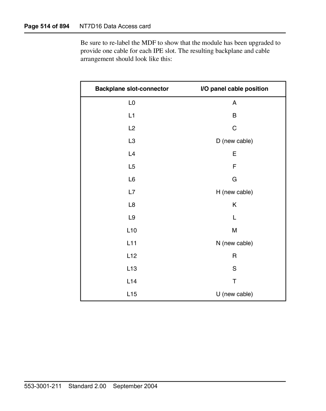
Segment
NT7D16 Data Access card Page 513
Backplane slot-connector Panel cable position
NT8D02 and NTDK16 Digital Line cards
NT8D02 Digital Line card
NTDK16 Digital Line card
Digital line card faceplate
518 of 894 NT8D02 and NTDK16 Digital Line cards
Digital line card block diagram
Interface
Digital line interfaces
NTDK16 DLC
TCM loop interface circuit
NT8D02 and NTDK16 Digital Line cards Page 523
524 of 894 NT8D02 and NTDK16 Digital Line cards
Digital line interface specifications
NT8D02 DLC NTDK16BA DLC NTDK16AA DLC
Digital line card-power required Voltage Current max
NT8D02 and NTDK16 Digital Line cards Page 527
528 of 894 NT8D02 and NTDK16 Digital Line cards
Jumper and switch settings
Digital line card jumper block and switch locations
NT8D02 and NTDK16 Digital Line cards Page 531
Page
NT8D03 Analog Line card
Overview
534 of 894 NT8D03 Analog Line card Standard 2.00 September
NT8D09 Analog Message Waiting Line card
Damage to Equipment
Type Digitone sets or equivalent
NT8D09 Analog Message Waiting Line card Page 537
Analog message waiting line card faceplate
NT8D09 Analog Message Waiting Line card Page 539
Analog message waiting line card block diagram
Data bus
Line interface units
542 of 894 NT8D09 Analog Message Waiting Line card
Frequency response
Input impedance
Insertion loss
Message channel noise
NT8D09 Analog Message Waiting Line card technical summary
Power requirements Voltage Idle Active Tolerance Current Max
Overload level
NT8D09 Analog Message Waiting Line card Page 547
System Cross-connect
NT8D09 Analog Message Waiting Line card Page 549
Transmission Profile Changes Vintage Convertor gain
NT8D09 Analog Message Waiting Line card Page 551
Page
NT8D14 Universal Trunk card
554 of 894 NT8D14 Universal Trunk card
Tie
Trunk and signaling matrix Trunk types Signaling type
CO/FX Did
RAN
556 of 894 NT8D14 Universal Trunk card
Universal trunk card faceplate
NT8D14 Universal trunk card block diagram
Codec Interface Control
Trunk interface units
560 of 894 NT8D14 Universal Trunk card
Signaling interface
Loop start operation
Polarity-sensitive/-insensitive packs feature
WATS/ farend
Signal/direction
564 of 894 NT8D14 Universal Trunk card
NT8D14 Universal Trunk card Page 565
Reverse-wiring compensation
Ground start operation
NT8D14 Universal Trunk card Page 567
Signal/direction Remarks
NT8D14 Universal Trunk card Page 569
CO/FX/WATSfar Battery on ring Ground on tip
End
NT8D14 Universal Trunk card Page 571
Direct inward dial operation
Two-way, loop dial repeating, TIE trunk operation
Low
State Signal/direction Remarks
NT8D14 Universal Trunk card Page 575
576 of 894 NT8D14 Universal Trunk card
NT8D14 Universal Trunk card Page 577
High-resistance
Battery on ring Loop
On tip On ring
NT8D14 Universal Trunk card Page 579
580 of 894 NT8D14 Universal Trunk card
NT8D14 Universal Trunk card Page 581
Senderized operation for did and two-way loop DR trunks
Far end PBX Low-resistance Loop Resistance High
584 of 894 NT8D14 Universal Trunk card
Outgoing automatic, incoming dial operation
See on page 589 and on
Battery on ring Loop Far end Ground on tip, battery on ring
On on
Far end First Disconnect High End
Low-resistance Battery-ground Or loop pulses
Resistance Far end
Or Dtmf
PBX
Farend Loop Resistance
High Far end
Answers
590 of 894 NT8D14 Universal Trunk card
Recorded announcement trunk operation
Recorded announcement machines
MDF
RAN modes of operation
Multi-Channel RAN modes
RAN control signals Control GRD = Idle
ST+
Continuous operation mode
Call routing to RAN trunks
Programming RAN trunks
CO / FX / Wats Did / TIE RAN
598 of 894 NT8D14 Universal Trunk card
PAD switching
Release control
600 of 894 NT8D14 Universal Trunk card
ESN E&M Wats
CO/FX
Line Trunk
Trunk Loop Tie IPE Ports
Back Trunk Plane
Universal trunk card backplane pinouts Part 1 Signal
Paging Other Number Pin Mode Modes
Paging Other Plane
68A Tip
Universal trunk card backplane pinouts Part 2 Signal
Back
69A
604 of 894 NT8D14 Universal Trunk card
NT8D14 Universal Trunk card Page 605
Oaid
Service change entries
NT8D14BB
137Figure
Release 9 and below
NT8D14 Universal Trunk card Page 609
610 of 894 NT8D14 Universal Trunk card
Port B to Universal Trunk
Pad switching algorithm Universal Trunk Port B pads
Port-to-port loss dB
Receive Trunk Card to Port B To a To D
Paging trunk operation
Music operation
Typical customer- provided external equipment
Page
NT8D15 E&M Trunk card
Trunk and signaling matrix Trunk types Signaling
RLM/RLR TIE PAG CSA/CAA/CAM
NT8D15 E&M Trunk card Page 617
Trunk card faceplate
Common features
Trunk card block diagram
NT8D15 E&M Trunk card Page 621
Trunk circuit features
Trunk unit functions
Type I signaling
Type II signaling
Sgsg
Wire DX signaling 143
Circuit
MDF
Paging trunk operation SystemCross connect
Card LAN
628 of 894 NT8D15 E&M Trunk card
Signaling and call control
Maintenance features
Type I signaling
Idle state
CO/FX Wats
Outgoing calls from near end
Type I signaling patterns originating party release
Incoming calls to near end
632 of 894 NT8D15 E&M Trunk card
IMM
Type II signaling
Operation Mode Operation mode Start arrangement
WNK
Duplex signaling
Release control
Outgoing calls from system near end
Type II signaling patterns originating party release
Incoming calls to system near end
636 of 894 NT8D15 E&M Trunk card
NT8D15 E&M Trunk card Page 637
638 of 894 NT8D15 E&M Trunk card
NT8D15 E&M Trunk card Page 639
640 of 894 NT8D15 E&M Trunk card
Lists the power requirements for the E&M trunk card
Power requirements Voltage Tolerance Max current
Environmental specifications Parameter Specifications
ECG
Number Pin Signal
Escg
644 of 894 NT8D15 E&M Trunk card
Trunk card typical cross connection example
Trunk Connections
Jumper settings
Trunk card jumper locations
Rcv
Type Paging Xmt
Software service entries
On page 651 shows the pad switching orientation
Receive Port B to To a To D
XMT
Pad orientation
REC
XMT REC
652 of 894 NT8D15 E&M Trunk card
Trunk Loop Tie IPE Ports Wire Wire ESN E&M Trunk
Shows the insertion loss from IPE port to IPE port
654 of 894 NT8D15 E&M Trunk card
NT8D41AA Serial Data Interface Paddle Board
656 of 894 NT8D41AA Serial Data Interface Paddle Board
LED
NT8D41AA SDI paddle board
NT8D41AA SDI paddle board block diagram
System considerations
RTS
CTS
Configuring the SDI paddle board
Clear to send Note
Option switch settings
DTE/DCE/Fiber mode
663
SDI paddle board option switch locations
Enable Backplane Mating Connectors
Iotb YES
REQ CHG
Type CFN
Adan
666 of 894 NT8D41AA Serial Data Interface Paddle Board
SDI paddle board cabling
Page
NT8D41BA Quad Serial Data Interface Paddle Board
670 of 894 NT8D41BA Quad Serial Data Interface Paddle Board
Disable
NT8D41BA Qsdi paddle board
NT8D41BA Qsdi paddle board block diagram
Uart
NT8D41BA Quad Serial Data Interface Paddle Board Page 673
674 of 894 NT8D41BA Quad Serial Data Interface Paddle Board
Configuring the Qsdi paddle board
676 of 894 NT8D41BA Quad Serial Data Interface Paddle Board
NT8D41BA address switch settings SW15 Port Switch settings
678 of 894 NT8D41BA Quad Serial Data Interface Paddle Board
Ctype SDI4
Type Adan
DES Xqsdi
680 of 894 NT8D41BA Quad Serial Data Interface Paddle Board
NT8D41BA Qsdi paddle board cabling
Page
MF signaling
NTAG26 Xmfr card
ST2PST
MF frequency values Backward direction Digit DOD-Tx, DID-Rx
STPST’
ST3PST
Xmfr receiver specifications
Tolerate Intermodulation
Xmfr receiver specifications Part 3
Excessive Components
Physical specifications
NTAK02 SDI/DCH card
NTAK02 SDI/DCH card
DCH OFF
Port configurations
Switch settings Port
DCH OFF Esdi
Jumper settings Strap for Port Location
Location RS422 RS232
BL-W DTR
Connecting to the ports
DTR RTS CTS BR-W
CH/CI DSR
Sctea
SCT Scteb Sctb
CTS RTS Scra Sctea SCR SCT
CH/CI
BK-G
BK-BR
BR-BK
Scra Sctea
Scteb Sctb CH/CI
CTS RTS
BL-V Scta Rxca SCT
Characteristics of the low speed port
Characteristics of the high speed port
NTAK09 1.5 Mb DTI/PRI card
NTAK09 DTI/PRI circuit card
ACT
NTAK09 LED states
DIS
LBK
NTAK20 power on self-test
NTAK09 DTI/PRI power on self-test
NTAK09 LED states during self-test Action LED State
DTI/PRI local self-test
NTAK93 self-test
Restrictions and limitations
702 of 894 NTAK09 1.5 Mb DTI/PRI card
Interconnection
Microprocessor
Digital pad
Digital pad values and offset allocations Offset PAD set
DS-1 Carrier interface
Channel interface
Transmitter
DCH F/W
Connector pinout
Receiver
LEN
Clock controller interface
Clock rate converter
Page
NTAK10 2.0 Mb DTI card
NEA
NTAK10 LED states Part 1
OOS
FEA
Environment
NTAK10 LED states Part 2
DS-30X interface
Applicability to France
Receive data
Transmit data
DS-30X microprocessor
Interconnections
Cept interface
Outgoing supervisory signals
Channel associated signaling
Incoming signal
MB DTI switch options Off Switch Switch Open Switch Closed
TS16 microprocessor
Carrier interface
Periodic Pulse Metering PPM
Change-of-state microprocessor
Rx Direction
Clocking modes
Tracking mode
Reference switchover
Clock controller functions and features
Autorecovery and chatter
Reference clock selection through software
Switch settings
Reference clock interface
722 of 894 NTAK10 2.0 Mb DTI card Standard 2.00 September
NTAK20 Clock Controller daughterboard
NTRB21 DTI/PRI/DCH Tmdi NTBK22 Misp NT6D70 Silc NT6D71 Uilc
724 of 894 NTAK20 Clock Controller daughterboard
Clocking modes
Free-run non-tracking
Faceplate LEDs
Faceplate LEDs State Definition
Phase difference detector circuit
Digital phase lock loops
Monitoring references
System clock specification and characteristics
EIA/CCITT compliance
Ccitt EIA
Digital to analog converter
CPU-MUX bus interface
Signal conditioning
Sanity timer
Holdover and free-run
EMI
External timing interface
Hardware integrity and regulatory environment
ESD
Page
NTAK79 2.0 Mb PRI card
NTAK79 LEDs Part 1
NTAK79 LEDs Part 2
NTAK79 LEDs Part 3
NTAK79 switches
LED DCH
NTAK79 card with switch locations
NTAK79
Switch SW2 Carrier Impedance Configuration
Switch SW1 Dchi Configuration
Switch SW3 Clock Controller Configuration
Switch SW4 Carrier Shield Grounding
Switch SW4 Down On Up Off
740 of 894 NTAK79 2.0 Mb PRI card
PAD SET
Digital PAD
Digital pad values and offset allocations Part 1
PAD
Digital pad values and offset allocations Part 2
Impedance matching
Impedance matching switch selection Cable Off
Carrier grounding
Receiver functions
Channel support interface
Cept transceiver
Slip control
Transmitter functions
Dchi special applications connection
Settings for the Dchi dip switch SW1 Switch Function Off
Dchi
Card-LAN interface
NTAK79 2.0 Mb PRI card Page 747
748 of 894 NTAK79 2.0 Mb PRI card
NTAK79 2.0 Mb PRI card Page 749
750 of 894 NTAK79 2.0 Mb PRI card Standard 2.00 September
NTAK93 D-channel Handler Interface daughterboard
752 of 894 NTAK93 D-channel Handler Interface daughterboard
Microprocessors
NTAK09 1.5 Mb PRI and NTBK50 2.0 MB PRI cards
DMA controller
Random Access Memory RAM
Counter/timer controller
Read Only Memory ROM
Port SDTI/PRI interface
Page
NTBK22 Misp card
758 of 894 NTBK22 Misp card
CPU to Misp bus interface
High-Level Data Link Controller Hdlc
Misp network bus interface
760 of 894 NTBK22 Misp card
NTBK50 2.0 Mb PRI card
762 of 894 NTBK50 2.0 Mb PRI card
NTBK50 2.0 Mb PRI card with daughterboards
LEDs are described in Table
NTBK50 faceplate LEDs Part 1
NTBK50 faceplate LEDs Part 2
766 of 894 NTBK50 2.0 Mb PRI card
NTBK50 2.0 Mb PRI card Page 767
768 of 894 NTBK50 2.0 Mb PRI card
Impedance matching Switch SW2
Impedance matching switch settings Cable Type
Carrier Shield grounding Switch SW4
Lists the Carrier Shield ground switch settings
Dchi Configuration for NTAK93 only SW1
Dpnss Dchi
NTBK51 Downloadable D-channel Handler daughterboard
Faceplate LED State Definition
NTBK51 Downloadable D-channel Handler daughterboard Page 775
Eprom memory
Main memory
Shared memory
Flash Eprom memory
System initialization
Bus timer
Download operation
Card enabling or application enabling
Card reset
Background audit
NTCK16 Generic Central Office Trunk cards
780 of 894 NTCK16 Generic Central Office Trunk cards
Self-test
Idle state
Central Office disconnect
Call placed by Central Office
Call placed by CS 1000S, CS 1000M, and Meridian
CS 1000S, CS 1000M, and Meridian 1 disconnect
784 of 894 NTCK16 Generic Central Office Trunk cards
Cross connections
786 of 894 NTCK16 Generic Central Office Trunk cards
NTCK16 Generic Central Office Trunk cards Page 787
788 of 894 NTCK16 Generic Central Office Trunk cards
NTCK16AX Central Office trunk card
Route Data Block
Trunk Data Block
CLS LOL SHL
DTN, DIP
NTCK16BX Central Office trunk card
LD 16 Route Data Block for NTCK16BX
LD 14 Trunk Data Block for NTCK16BX. Part 1
BAT CLS LOL SHL
LD 14 Trunk Data Block for NTCK16BX. Part 2
DIP DTN
Periodic Pulse Metering
Btid values by country
Detection limits
Loss switching
Busy tone detect
400 to 620 Hz
Natp YES
REQ CHG Type Sysp
REQ CHG Type COT Xtrk Xcot Sigl LOP CLS LOL
Call disconnect
Trunk to Trunk connection
Equivalencies
NTDK20 Small System Controller card
800 of 894 NTDK20 Small System Controller card
Flash ROM Drive
Memory
NTTK25 daughterboard
100BaseT IP daughterboards
804 of 894 NTDK20 Small System Controller card
NTTK34AA UTP CAT
PC card interface
Call Server connection to Media Gateway 1000S systems
Security device
10BaseT port
SDI ports
Conferencing
MTC/SCH
MG 1000S/Expansion card slot assignment
810 of 894 NTDK20 Small System Controller card
Media Gateway
MG 1000S slots
MG 1000S Expansion slots
NTRB21 DTI/PRI/DCH Tmdi card
814 of 894 NTRB21 DTI/PRI/DCH Tmdi card
NTRB21 Tmdi card with clock controller
On page 817 shows the faceplate of the NTRB21 Tmdi card
NTRB21 LED states
NTRB21 Tmdi card faceplate
818 of 894 NTRB21 DTI/PRI/DCH Tmdi card
Hardware description
Software description
NTRB21 Tmdi card
820 of 894 NTRB21 DTI/PRI/DCH Tmdi card
NTRB21 DTI/PRI/DCH Tmdi card Page 821
822 of 894 NTRB21 DTI/PRI/DCH Tmdi card
NTRB21 DTI/PRI/DCH Tmdi card Page 823
824 of 894 NTRB21 DTI/PRI/DCH Tmdi card
NTAK20 Clock Controller CC daughterboard
Clock rate converter
NTVQ01xx Media Card
NTVQ01xx Media Card
Faceplate connectors and indicators
Hardware architecture
NTVQ01xx Media Card faceplate
RS-232 Asynchronous Maintenance Port
Survivability
832 of 894 NTVQ01xx Media Card Standard 2.00 September
NTVQ55AA ITG Pentium card
Faceplate components
ITG-P LED Card Status
Onboard Flash Drive C
NTVQ55AA ITG-P card faceplate
Backplane interfaces
Maintenance Display
RS-232 Maintenance Port
NWK Status LED
Assembly description
DS-30X voice/signaling
838 of 894 NTVQ55AA ITG Pentium card Standard 2.00 September
QPC513 Enhanced Serial Data Interface card
840 of 894 QPC513 Enhanced Serial Data Interface card
CPC513 Esdi card front panel
Esdi
Esdi card block diagram
RAM
Characteristics of synchronous ports Part 1 Description
Synchronous communication
Clock timing option
Test and maintenance features
Characteristics of synchronous ports Part 2 Description
Self-test
Fault detection
Connection characteristics
Fault isolation
Electrical interface options
Typical high-speed interface line driver and receiver
Control
Data
Timing
From Circuit Pin number Signal functions To DCE
Pin number Signal functions To DCE From DCE Circuit
Ground Common return
QPC513 Enhanced Serial Data Interface card Page 849
Configuring the Esdi card
Address switch settings
DTE/DCE mode jumper settings
Esdi card option switch locations
Esdi card RS-232-C/high-speed interface jumper settings
Esdi card DTE/DCE mode jumper settings
Mode Port Designations
UA9
854 of 894 QPC513 Enhanced Serial Data Interface card
QPC513 Enhanced Serial Data Interface card Page 855
QPC513 Esdi card cabling
QPC841 Quad Serial Data Interface card
858 of 894 QPC841 Quad Serial Data Interface card
QPC841 Qsdi card front panel
860 of 894 QPC841 Quad Serial Data Interface card
QPC841 Qsdi card block diagram
FGD
QPC841 Quad Serial Data Interface card Page 863
Configuring the Qsdi card
Address switch settings
Pair Addresses
Baud rate switch settings
Lists the switch settings necessary to set the baud rate
Port 2 SW6 Port 2 SW7 Mode
DTE/DCE mode switch settings
Test switch setting
Port 3 SW4 Port 3 SW5 Mode
Qsdi card option switch locations
QPC841 Quad Serial Data Interface card Page 869
870 of 894 QPC841 Quad Serial Data Interface card
QPC841 Qsdi card cabling
Page
TDS/DTR card
Tone detector
Tone transmitter
SDI function
Tone # Overload
Tones and cadences
Dtmf
Digits MF Digits
400
TDS/DTR card Page 877
KP/CR/KP1
ST3P/RB
STP/C12
ST2P/KP2
TBD
Tone # Frequency Hz Overload
TDS/DTR card Page 881
Dtmf
TDS/DTR card Page 883
420 X
TDS/DTR card Page 885
188
TDS/DTR card Page 887
17/-15 235
Appendix a Lapb Data Link Control protocol
Frame structure
Combined station
Lapb balanced class of procedure
Balanced configuration
FCS
Asynchronous Balanced Mode
Commands and responses
Balanced configuration
Commands and responses Response Option
Description of procedure
Sabm
Page
Page
Description and Installation
Circuit Card