FR-F500
This section is specifically about safety matters
Safety Instructions
Additional instructions
Emergency stop
Treat as industrial waste
Contents
100
102
103
104
163
Watt-hour meter clear/actual operation hour meter clear
192
184
195
Chapter Outline
Chapter
Precautions for operation
Installation
Wiring
Pre-Operation Information
Basic Configuration
Basic configuration
Japanese Harmonic Suppression Guideline
Name Description
Structure
Appearance and structure
Front view
Without front cover
Removal and reinstallation of the front cover
FR-F520-0.75K to 11K, FR-F540-0.75K to 11K
FR-F520-30K to 55K, FR-F540-30K to 55K
Removal and reinstallation of the operation panel
Chapter
Installation
Instructions for installation
Clearances around the inverter
97inches1.97inches
For installation in an enclosure
Wiring cover and handling 22K or less
Vertical mounting
NFB
Symbol Terminal Name Description
Type Symbol Terminal Name Description
Description of main circuit terminals
Description of control circuit terminals
Type
Terminal Name Description
RUN
IPF
Wiring of the main circuit
Wiring instructions
Overall wiring length 1.5K or more
Inverter Capacity 75K 5K or more
Motor Capacity Ground Cable Gauge 200V class 400V class
Terminal block layout
FR-F520-1.5K, 2.2K, 3.7K FR-F520-45K
FR-F520-5.5K, 7.5K FR-F520-55K
FR-F520-11K
400V class FR-F540-0.75K, 1.5K, 2.2K, 3.7K FR-F540-30K, 37K
FR-F540-5.5K, 7.5K, 11K FR-F540-45K, 55K
FR-F540-15K, 18.5K, 22K
Terminal names in parentheses are those of the EC version
Connection of the power supply and motor
Cables, crimping terminals, etc
Model FR-F520-0.75K to 3.7K, FR-F540-0.75K to 3.7K
Connection procedure
Model FR-F520-5.5K to 55K, FR-F540-5.5K to 55K
Wiring of the control circuit
Terminal screw size M3.5 Tightening torque 1.2 N⋅ m
Changing the control logic
Current flow related to RUN signal
How to use terminals STOP, CS and PC
Connection to the PU connector
Recommended cable connector
PU connector pin-outs
System configuration example
Wiring method
Wiring of one RS-485 computer and one inverter
RS-485 terminal Computer
Max m
Connection of stand-alone option units
Connection of the FR-BU brake unit option
Connection of the FR-HC high power factor converter option
Connection of the conventional BU brake unit option
Connection of the FR-RC power regeneration converter option
Connection of the power factor improving DC reactor option
Design information
Interlock Power Supply MC2 Leakage current
MC1
Power harmonics
Other wiring
Harmonics RF Noise
Received Power 5th 7th 11th 13th 17th 19th 23rd Over 23rd
Japanese harmonic suppression guidelines
Conversion Factors for FR-F500 Series
Class Circuit Type
Harmonic Content Values at the fundamental current of 100%
Equivalent Capacity Limits
ACL, DCL
Harmonic suppression techniques
FR-HC
Inverter-generated noises and reduction techniques
Data line filter
Noise Path Measures
Following measures must be taken
Bundle them
Noise Induced to Signal Cables by Inverter Output
Data examples
Noise Terminal Voltage of Inverter and Example
Its Reduction by Noise Filters
Leakage currents and countermeasures
To-ground leakage currents
# Example of counter measures against noise
# Countermeasures
Inverter-driven 400V class motor
Line-to-line leakage currents
Rectifying the motor insulation
Suppressing the surge voltage on the inverter side
Selection of peripheral devices
Peripheral devices
400V class
Example
Standard to comply UL 508C 1 Installation
Wiring of the power supply and motor
Branch circuit protection
Short circuit ratings
Instructions for compliance with the European standards
Motor overload protection
EMC Directive
Our view of transistorized inverters for the EMC Directive
Low Voltage Directive
During operation Storage During transportation
90% RH or less
Maximum Altitude 000 m 10,000 m
Earthing EC version
Earthing and Earth Leakage Current
Earthing methods
Unit mm2
OPERATION/CONTROL
External operation mode factory setting
PU operation mode
External/PU combined operation mode
Devices and parts to be prepared for operation
Communication operation mode
Power on
Before switching power on, check the following
Operation Panel
Names and functions of the operation panel FR-DU04
Key indications
Unit indications, operating status indications
Used to set the running frequency in the PU operation mode
Frequency setting
Monitoring
Parameter setting method
Help mode
Operation mode
Alarm history
Alarm history clear
Parameter clear
All clear
User clear
Copy mode
#Parameter setting mode
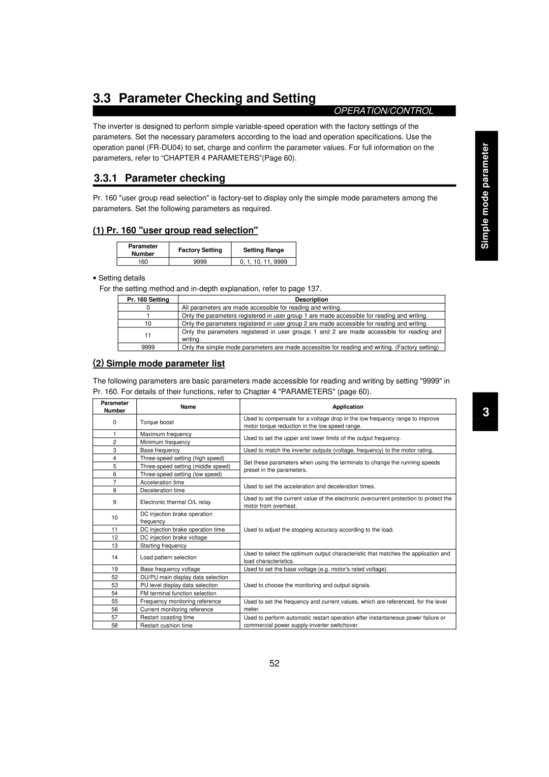
Parameter Checking and Setting
Simple mode parameter list
Parameter checking
Pr user group read selection
Name Application
Main parameter settings
Setting of maximum frequency Pr maximum frequency
Setting of minimum frequency Pr minimum frequency
Parameter Factory Setting
Application Setting
Selection of load pattern Pr load pattern selection
Gain
0Hz at 4mADC, 60Hz at
Operation
Pre-operation checks
External jog operation
Operation at 60Hz
Description Image
PU jog operation
Start Press
Stop Press
Motor is decelerated to a stop
Decelerates when Pr = 9999 to a stop
Step Description
Start
Hold down the key to change the frequency
Parameters
Parameter List
Parameter list
Setting Tion
F4 fourth frequency voltage
Minimum Factory Refer Cust Func Parameter Setting
Can be accessed when Pr =
PID
List of Parameters Classified by Purposes of Use
Function rewrite prevention
Setting
Parameter Factory Setting Range Remarks
Parameter Function Details
Torque boost Pr , Pr
Use Pr to set the lower limit of the output frequency
Pr maximum frequency Pr minimum frequency
120Hz To 120Hz
8888
Base frequency, base frequency voltage Pr , Pr , Pr
9999 To 120Hz Function invalid
Multi-speed operation Pr to Pr , Pr to Pr.27
Parameter Factory Setting Setting Range Remarks
60Hz To 120Hz 30Hz 10Hz 24 to 9999
To 3600 s minimum setting increments 0.1 s
To 360 s minimum setting increments 0.01 s
Factory Setting Range Remarks
Acceleration/deceleration time Pr , Pr , Pr , Pr , Pr , Pr
Electronic overcurrent protection Pr
Pr electronic thermal O/L relay
Acceleration
Decelerationtime s
DC injection brake Pr to Pr
Operated at
Value Operated
To 10 s
Pr starting frequency
Starting frequency Pr
5Hz To 60Hz
Parameter Factory Setting Range
Output Characteristics
Load pattern selection Pr
Pr load pattern selection
Pr jog acceleration/deceleration timereference frequency
Jog operation Pr , Pr
Pr jog frequency
Related parameters
Wiring example
Pr Setting Specifications of MRS Signal
MRS input selection Pr
Pr MRS input selection
Parameter Number Factory Setting Setting Range Remarks
Stall prevention Pr , Pr , Pr , Pr , Pr , Pr
To 120Hz 148
149
Multi-speed input compensation Pr
Pr multi-speed input compensation
Not compensated
Compensated
Acceleration/deceleration pattern Pr , Pr.140 to Pr.143
Function Description
Setting When using the brake unit, power return converter
When using the high power factor converter FR-HC
Regenerative brake duty Pr.30
Pr regenerative function selection
Frequency jump Pr to Pr
Pr.3335Hz Pr.3430Hz
Pr speed display Pr speed setting switch-over
Running Speed Parameter Setting Unit Pr Setting
Speed display Pr , Pr
144 4, 6, 8, 10 104, 106, 108
Factory Setting Setting Range Setting Capacity
Automatic torque boost Pr , Pr
Up-to-frequency sensitivity Pr
Pr up-to-frequency sensitivity
Output Signal
6Hz To 120Hz 9999 Same as Pr Setting
Output Signal
Output frequency detection Pr , Pr , Pr
Pr Setting Operation
Second stall prevention Pr , Pr
120%
Second stall prevention function is not activated
Parameter Number Factory Setting Setting Range
Set Pr to Pr and Pr in accordance with the following table
Output frequency monitor
Output current monitor
Set value 17, 24 monitor
100
Setting Parameter
Monitoring reference Pr , Pr
Maximum output voltage of terminal AM is 10VDC
To 120Hz Rated output
Parameter Factory Setting Remarks
9999 1 to No restart
Frequency 162 Search No frequency 163
164
Parameter Setting Description
To the load inertia moment, torque 165
Remote setting function selection Pr
Pr remote setting function selection
FrequencyOutput
Intelligent mode selection Pr
Pr intelligent mode selection
Operation Mode Description Automatically Set
Ordinary operation
Setting Pr Reference I for intelligent mode
Pr Ref. I for intelligent mode accel
Pr Ref. I for intelligent mode decel %
Setting Reference Current
Use Pr to select alarms to be reset for retry
Errors Reset for Retry Setting
Retry function Pr , Pr to Pr
P24
Retry is not made
Use Pr to set the number of retries at alarm occurrence
To 10 times Not output 101 to Output
Pr applied motor
Applied motor Pr
Motor
Pr PWM frequency selection Pr Soft-PWM setting
Parameter Factory Setting Description
PWM carrier frequency Pr , Pr
Refer to the following list and set the parameters
Voltage input Pr
Pr 0-5V/0-10V selection
Related parameters
To 5, 10 to
Input filter time constant Pr
Reset Selection PU Disconnection Detection
Pr filter time constant
Key from the PU during
Alarm code output selection Pr
Pr alarm code output selection
Alarm code output
Pr Setting Output Terminals
Parameter write inhibit selection Pr
Pr parameter write disable selection
Parameter Name
Reverse rotation prevention selection Pr
Pr reverse rotation prevention selection
Operation mode selection Pr
Pr operation mode selection
External signal input terminal STF, STR
To 4, 6 to
PU operation interlock
Switch-over mode
X12 MRS Function/Operation
Operation mode external signal switching function
X16 Signal Operation Mode
Operating Condition
X12 MRS
38 V/F control frequency voltage Pr to Pr
Confirm the settings of Pr , Pr and Pr
Parameter Number
Computer link operation Pr to Pr
Parameter Factory Setting Range Number
Parameter Description Setting
117 118 192 119 Data length 120 121 To 10 122 9999
123 9999 To 150ms 124
Computer programming Communication protocol
Required after no data error ACK. Refer to
Data format
Data definitions
Reply data from inverter to computer during data read
Send data from computer to inverter during data read
Control codes
Response time
= Data sending time s
Number of Bits
Stop bit length Bit Bits Data length Parity check
H7F
Instruction Data
HFF
Instructions for the program
Return
Setting items and set data
Instruction
HFA
H7A
H6E
H6D
Error Code List
Error Definition Inverter Operation
H6C
HEC
Communication specifications for RS-485 communication
Operation at alarm occurrence
Communication error
Operation Mode Operation Location
Setting Basic PID control configuration
PID control Pr to Pr
Pr = 10
Pr = 20
PID action overview
Sink logic
Pr =
Deviation
Reverse action Forward action
O signals
Signal
Function Description Remarks
Entry Description
Parameter setting
Adjustment procedure
Gain K = 1/proportional band 9999
132
Calibration example
Start
Set point input calibration
Detector output calibration
137
135 136
138 139 9999 To 60.0Hz No automatic
Sink logic, Pr = 7, Pr = 6, Pr = 17, Pr = 18, Pr =
NFB MC1
Signals
Magnetic Place of Installation Role
Signal Terminal Used Description
Roles of the magnetic contactors MC1, MC2, MC3
Parameter Name Setting Description
Commercial power To 60.0Hz 139
Operation sequence
Sets the MC2 and MC3 operation interlock time
Operation procedure
Operation procedure for running Operation pattern
Signal on-off after parameter setting
OFF OFF →
Pr to Pr % Refer to Pr Pr , Pr % Refer to Pr
Zero current detection Pr , Pr
Zero current detection level
Zero current detection period
Related parameters Pr to Pr
RT signal activated condition selection Pr
Pr RT signal activated condition
Stall prevention function and current limit function Pr
Pr stall prevention operation selection
#...Operation not #...Not activated Acceleration
Deceleration
100 Driving
101 Driving
OL signal output timer Pr
Pr OL signal waiting time
157 To 25 s No signal output
Related parameters Pr RUN terminal function selection
User group selection Pr , Pr to Pr
Examples of use
160 9999 10, 11 173 174
Batch deletion
184 Current input selection AU For the NA and EC 185
Input terminal function selection Pr to Pr
Jog operation selection JOG
Setting Signal Functions Relevant Parameters
Output terminal function selection Pr to Pr
Refer to the following table and set the parameters
Commercial power supply Inverter switch-over MC1
Commercial power supply Inverter switch-over MC3 125
FAN
Sleep
User initial value setting Pr
Pr users initial value setting
Setting example
199
Output phase failure protection selection Pr
Pr output phase failure protection selection
Cooling fan operation selection Pr
Pr cooling fan operation selection
Override bias/gain Pr , Pr
Pr override bias Pr override gain
50%
150%
Advanced PID control Pr to Pr NA, EC versions only
Pr motor switch-over selection = 0 Basic Method
Pr motor switch-over selection = 1 Alternative Method
Pr =0
Pr =1
System configuration
Pr motor switch-over selection = 2 Direct Method
Pr motor switch-over selection = 0 Basic Method Example
DC24V
Signal name Function
Parameter Number Name Additional Setting Description
Parameter Number Name
Start Stop
Motor switch-over timing
Start
Name Setting Range
Output stop detection
Stopstart
M1 operation
Status transition chart
Sleep
EC version 50Hz
Commercial power
Supply operation
Meter frequency meter calibration Pr , Pr
Pr FM terminal calibration Pr AM terminal calibration
Calibration of terminal FM
Calibration of terminal AM
Operation procedure
When operation panel FR-DU04 is used
Frequency setting voltage current bias and gain Pr to Pr
902 0Hz To 60Hz 903
904 4mA 0Hz To 20mA To 60Hz 905
To 20mA To 120Hz
Mode
Power-on monitoring mode
Mode
#Setting change
#Parameter setting mode
Least significant
To 90 to Current setting of gain frequency
Press to change the set frequency Press for 1.5 s
# Analog voltage A/D value % Across terminals
⋅ 9 times
Analog voltage calibration value 5V 10V, 20mA
Once to display the current For 0V 0mA, 100% for
#Press
Pr buzzer control
Buzzer control Pr
990 Without beep, 1 With beep
Protective Functions
Error alarm definitions
Errors Alarms
Major faults
OC During Dec
OV During Acc
Check for too slow acceleration
Decrease the acceleration time
Find the cause of instantaneous power failure occurrence
Instantaneous power failure is within 15ms
Remedy the instantaneous power failure
Set the ambient temperature to within the specifications
Ground Fault
Output side ground fault overcurrent protection
Check for a ground fault in the motor and connection cable
Option slot alarm 1 to
Check for a wrong option function setting and operation
Check the communication cable for wire breakage
Parameter storage device alarm
Find the cause of alarm occurrence
CPU Fault
Fault
CPU error
Check for a short circuit in the PU connector cable
Output phase failure protection
P24
Check for a short circuit in the PC terminal output
Minor fault
Reduce the load volume or the frequency of operation
PU stop Stop made by pressing
Key of the PU has been set in Pr PU
Stop selection
Correspondences between digital and actual characters
To know the operating status at the occurrence of an alarm
Actual Digital
Resetting the inverter
Alarm code output
Key to reset the inverter
Troubleshooting
Speed greatly differs from the setting
Motor remains stopped
Motor rotates in opposite direction
Operation mode is not changed properly
Power lamp is not lit
Motor current is large
Speed does not increase
Precautions for Maintenance and Inspection
Precautions for maintenance and inspection
Check items
Periodic inspection
Pressure test
Insulation resistance test using megger
Daily and Periodic Inspection
Disconnect cables
Inspection Description Periodic Method Crlterlon Instrument
Analog meter Converter Across terminals
Checking method
Module device numbers and terminals to be checked
Assumes the use of an analog meter
Tester Polarity Measured Value
Replacement of parts
Part Name Standard Replacement Interval Description
Cooling fan
Smoothing capacitor in main circuit
Smoothing capacitors
Inverter replacement
Relays
Measurement of voltages and currents
Measurement of main circuit voltages, currents and power
Typical Measuring Points and Instruments
Measuring Points and Instruments
Measuring Point
5VDC
10VDC
Specifications
Standard Specifications
Model specifications
Voltage, frequency Permissible AC
36.0
Setting To +10V, 11 bits/-5 to +5V
Common specifications
Collector output
Alarm
Outline drawings
Unit mm inches
# FR-F520-5.5K, 7.5K, 11K # FR-F540-5.5K, 7.5K, 11K
Unit mm inches
Inverter Type FR-F520-37K 340 270 320 550 530 195 71.5
FR-F520-45K 450 380 430 550 525 250 154
FR-F520-55K 480 410 460 700 675 250 154
W1 W2 H H1 FR-F540-30K,37K 340 270 320 550 195 71.5
Outline drawing Panel cutting dimension drawing
# Operation panel FR-DU04
Chapter Options
Option List
Stand-alone options
193
Inboard dedicated options
Name Type Function
Appendices
Appendix Data Code List
Multi-speed setting speed
Data Codes
Read
118 Communication speed
PID
Read Write
Func
Name Read
Motor switch-over selection
Output stop cancel process value level
Auxiliary motor start delay frequency
Auxiliary motor stop delay frequency
Manual number is given on the bottom left of the back cover
Print Data Manual Number Revision