|
|
|
| Chapter 4 Parameters |
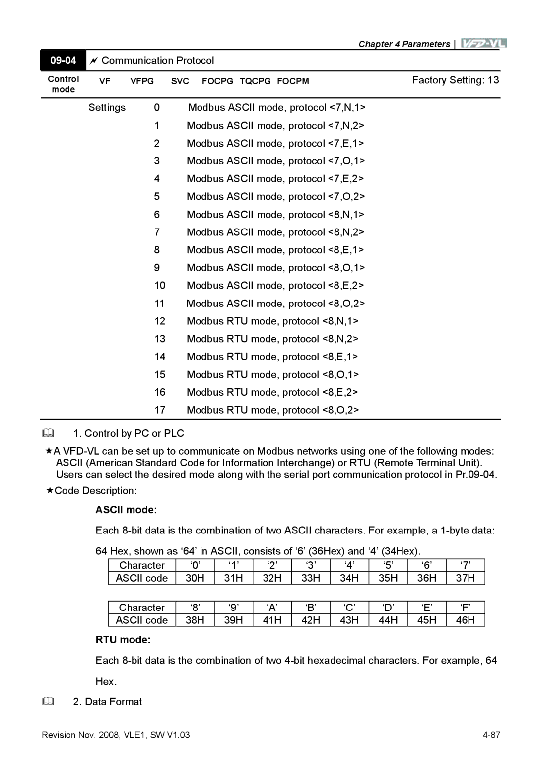
| Communication Protocol |
| ||
|
|
|
|
|
Control | VF | VFPG | SVC FOCPG TQCPG FOCPM | Factory Setting: 13 |
mode |
|
|
|
|
| Settings | 0 | Modbus ASCII mode, protocol <7,N,1> | |
1Modbus ASCII mode, protocol <7,N,2>
2Modbus ASCII mode, protocol <7,E,1>
3Modbus ASCII mode, protocol <7,O,1>
4Modbus ASCII mode, protocol <7,E,2>
5Modbus ASCII mode, protocol <7,O,2>
6Modbus ASCII mode, protocol <8,N,1>
7Modbus ASCII mode, protocol <8,N,2>
8Modbus ASCII mode, protocol <8,E,1>
9Modbus ASCII mode, protocol <8,O,1>
10Modbus ASCII mode, protocol <8,E,2>
11Modbus ASCII mode, protocol <8,O,2>
12Modbus RTU mode, protocol <8,N,1>
13Modbus RTU mode, protocol <8,N,2>
14Modbus RTU mode, protocol <8,E,1>
15Modbus RTU mode, protocol <8,O,1>
16Modbus RTU mode, protocol <8,E,2>
17Modbus RTU mode, protocol <8,O,2>
1. Control by PC or PLC
A
ASCII (American Standard Code for Information Interchange) or RTU (Remote Terminal Unit). Users can select the desired mode along with the serial port communication protocol in
Code Description:
ASCII mode:
Each
64 Hex, shown as ‘64’ in ASCII, consists of ‘6’ (36Hex) and ‘4’ (34Hex).
Character | ‘0’ | ‘1’ | ‘2’ | ‘3’ | ‘4’ | ‘5’ | ‘6’ | ‘7’ |
ASCII code | 30H | 31H | 32H | 33H | 34H | 35H | 36H | 37H |
Character |
|
|
|
|
|
|
|
|
‘8’ | ‘9’ | ‘A’ | ‘B’ | ‘C’ | ‘D’ | ‘E’ | ‘F’ | |
ASCII code | 38H | 39H | 41H | 42H | 43H | 44H | 45H | 46H |
RTU mode:
Each
Hex.
2. Data Format
Revision Nov. 2008, VLE1, SW V1.03 |