Chapter 11 FXYBX/SXYBX
4-1-3 User I/O cable specifications
!CAUTION
Securely crimp the pin and insert into the pin connector.
Failure to do so will prevent the signals and power from being supplied cor- rectly, and may prevent the device from operating correctly.
With the cable carrier model, signal wires (0.3mm2 ⋅ 10 wires) that can be used freely by the user are laid as a standard between the
Connectors and pins fitted onto the connectors on both ends of this signal wire are also enclosed. Attach these to the user wiring to eliminate wiring led through the robot.
Crimp the enclosed pins onto the user wiring, and insert into the connector.
Recommended crimping tool
Refer to
4-2 Whipover cable type
!CAUTION
Do not clamp the wires or tubes to the outside of the independent cable. The independent cable could sag or break and ultimately be disconnected.
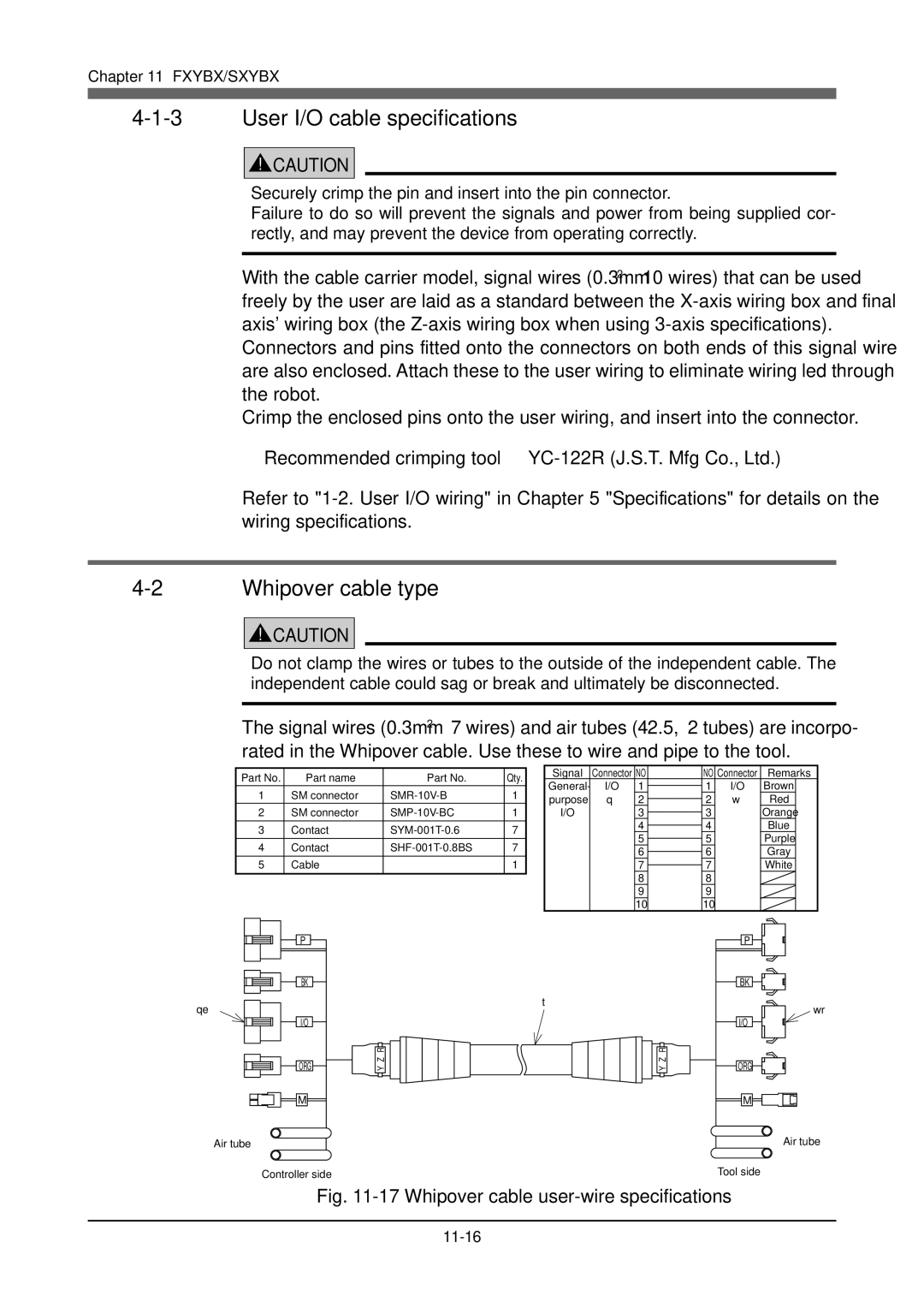
The signal wires (0.3mm2 ⋅ 7 wires) and air tubes (4 ⋅ 2.5, 2 tubes) are incorpo- rated in the Whipover cable. Use these to wire and pipe to the tool.
Part No. | Part name | Part No. | Qty. | Signal | Connector NO | NO Connector | Remarks | |||
General- | I/O | 1 | 1 | I/O | Brown | |||||
1 | SM connector | 1 | ||||||||
purpose | q | 2 | 2 | w | Red | |||||
|
|
|
| |||||||
2 | SM connector | 1 | I/O |
| 3 | 3 |
| Orange | ||
3 | Contact | 7 |
|
| 4 | 4 |
| Blue | ||
|
| 5 | 5 |
| Purple | |||||
4 | Contact | 7 |
|
|
| |||||
|
| 6 | 6 |
| Gray | |||||
|
|
|
|
|
|
| ||||
5 | Cable |
| 1 |
|
| 7 | 7 |
| White | |
|
|
|
|
|
| 8 | 8 |
|
| |
|
|
|
|
|
| 9 | 9 |
|
| |
|
|
|
|
|
| 10 | 10 |
|
| |
| P |
|
|
|
|
|
| P |
| |
| BK |
|
|
|
|
|
| BK |
| |
qe |
|
|
| t |
|
|
|
| wr | |
|
|
|
|
|
|
|
| |||
| I/O |
|
|
|
|
|
| I/O |
| |
|
| R |
|
|
|
| R |
|
| |
| ORG | Y Z |
|
|
|
| Y Z | ORG |
| |
| M |
|
|
|
|
|
| M |
| |
Air tube |
|
|
|
|
|
|
|
| Air tube | |
Controller side |
|
|
|
|
|
| Tool side |
| ||