Merlin
1988 AT&T Issue All Rights Reserved
Contents
About the Merlin II Communications System
Easy to USE Efficient Cost Effective
About the System Documentation
Documentation
Guides
HOW to USE
System Manual
Making Changes to a Running System?
Overview
Types of Voice Terminals
HOW Entries are Organized
General Procedures for Administration and Programming
Entering and Leaving Administration Mode
At an Analog Voice Terminal
At a Digital Voice Terminal
Account Code Entry
Description Considerations Programming HOW to USE
Abbreviated Ringing
See Ringing Options
With a Merlin II System Display Console
Description Considerations Administration
Allowed Lists
To Give Voice Terminals Access to Allowed Lists
Touch Message Dial #4 Dial the number of the list 0 through
Attendant Barge-In
Description
Attendant Postion Setting
Description Considerations
With a BIS-34D Console
Go on to another procedure, or leave administration mode
Auto Answer-All
Programming HOW to USE
Auto Answer-Intercom
Touch Auto Answer-Intercom again
Auto Intercom
Touch Auto Answer-Intercom
Automatic Line Selection
Tie Lines Uses An alternate long distance company
Considerations Administration
Automatic Route Selection
Merlin 11 System Features
Touch Message
If you enter These tables are 6-digit
Administering the Pool, Absorb, and Other Digits Sections
If you hear a fast busy signal again
To place a outside call using ARS
If you hear a busy signal that is faster than normal
Button is already on
Basic Telephones
Lines
Behind-Switch Operation
Fixed Features
Ringing Patterns
More, BehindSw
Local Conference, Drop, and Transfer Buttons
Speed Dial Access Button
Touch Conference, Drop, or Transfer
BIS/HFAI Terminal I d g i n g
Call Coverage
Description Considerations Programming
Call Forwarding and Follow Me
Activating Call Forwarding
Canceling Call Forwarding
Canceling Follow Me
Touch Call Forwarding
Call Park
Touch Call Park
Call Pickup
Touch Intercom-Ring or Intercom-Voice
To the button shows the appropriate code
Call Pickup Groups
Dial a group number 01 through
Call Report
Setting the System Time and Date with a BIS-34D Console
Console
Specifying Call Report Options with a BIS-34D Console
Outward Call Restriction. Restricts
Resetting the Printer with a BIS-34D Console
Call Restriction
Toll Call Restriction. Restricts voice
Identifying Toll Types for Selected Lines
Touch Speaker Touch Adm Tel
M p O n
Touch Speaker
Touch Recall
Considerations Administration Programming
Centralized Programming
From the administration menu, touch More, More, CntrPrg
Red light next to Adm Tel goes on
Button location codes for analog voice terminals
Message Shift
Speaker
Touch Conference
Description Considerations HOW to USE
Conference
Touch Coverage Inhibit
Coverage Inhibit
Touch Drop
Dialing Timeout Interval For Rotary Lines
Direct Inward System Access
To place a call using Disa
Dial the Disa password, if required
Time-keeping features Display screen
S p l a y
7406D Voice Terminal with Display Display screen
Merlin II System Display Console
Characters at a time
Display voice terminal that you are using
Display line can have a maximum of 16 characters. Each line
Being used, the screen shows the time, day, and date
Administration Mode
Account Code Entry
Caller ID
Touch Time/Timer
Call Coverage
Touch Clock Functions
To start the timer for calls you need to time
Stop
You see the following Clock Functions display
Exit
Clock Set Functions 930a Tue Time Day
Time Set Functions 930a Tues Hour Min
Set Date Month 930a Tue
Alarm Set Functions Hour Hour Min Min Exit
Timer Functions 930a 0000 Start Stop Reset
Alarm Functions 930a 1030a
Leave Word Calling
Number Dialed
Not Programmable
Program Mode
Blank
Timer The Merlin II System Display Console
Timer The 61 S-340 and SP-34D Voice Terminal
Timer The 7406D Voice Terminal
Transfer Return Identification
Touch Do Not Disturb
This feature remains active until you
Do Not Disturb
Touch Do Not Disturb again
O p
Extended Station Status
Appropriate procedures below
Select Hotel or CMS as appropriate
Dial #330
Flexible Numbering
64MERLIN II System Features
Block Renumbering
Type in the first lowest-numbered new dial code
Single Renumbering
Follow Me
Forced Account Code Entry
Programming
Dial # 22, the code for the Account Code entry feature
Just follow the standard Account Code Entry procedure
Number. If your system has ARS and you get a busy signal on
Procedure
Group Call Distribution
Touch Intercom-Voice Or Intercom-Ring
E a k e r p h o n e
To transfer an outside call to a Call Distribution group
Group Listening
Group
Touch Transfer
Voice terminals 1 through
To assign voice terminals to paging groups
Dial #88
Assign or remove voice terminals
Touch Hold
L d
Touch Intercom-Voice
Hold Disconnect Interval
Touch line buttons
Intercom
Touch Intercom-Ring
Match the CO line dial tone
To set the dial tone using a BIS-34D Console
Intercom Dial Tone
Labels for Stations
Merlin II Display Console in Administration Mode
Last Number Redial
Leave Word Calling
7406 Display Voice Terminals
Dial this
Label the button Programming code
Lights Meaning of the Lights
Lights
Speakerphone, and Microphone Buttons
Turn on your Message light
Message light. See Leave Word Calling
See Call Pickup
Line Assignments in Behind-Switch Systems
Line Pickup
I c e
Ring Message
Following codes
Touch the Auto Intercom button for the voice terminal
Station becomes available or try again later
When the copy is complete, the red light stops flashing
Line Assignments in Pooled Systems
Merlin II System Features
I c e Lntercom
Message
Been labeled at the voice terminals
Dial the pool code default codes are 9 and 890 through
Administration menu Stations, Line/Pool
Touch the line buttons until the correct code shows
Assigning Voice Terminals Dial Access to Line Pools
Touch Adm Pool
Red light next to Adm Tel flashes
On buttons at the voice terminals
Line Assignments in Square Systems
O i c e
Message
From Administration Menu Touch These
Touch Auto Intercom Button For Voice Terminal
Red light next to Adm Tel flashes
Description Cons Derations HOW to USE
Line Representation Line Request
Touch Line button
Touch Conference to return to Administration menu
Loudspeaker
Message
Manual Signaling
Touch Loudspeaker
Menu-Driven Administration
108MERLIN II System Features
Station Shift Buttons
Considerations HOW to USE
Line Shift Buttons
Data Entry Screens
Conference twice
Menu Selection Screens
Screen Abbreviations
Date
Cntr-Prg
Data
DayofWk
PageZone
OutOnly
OutRstr
PageZn
Considerations Programming HOW to USE
Message
Monitor-on-Hold
Dial # Wait until the system beeps twice
Night Service
Following procedure describes
Exclusion list From the administration menu, touch
118MERLIN II System Features
Them from Night Service groups
Enter
Dialing *39
Leave administration mode
Dial #907 and wait for the beep
Turning Night Service with Outward Restriction On and Off
Making a Call Using the Password
Notify
Terminal Touch the Send Button for That Voice
One-Touch Hold with Call Annoucement
On-Hook Dialing
That line
To use One-Touch Hold with Call Announcement
Group to whom you are placing an intercom call
Outside Auto Dial
Directions under Considerations
PBX, Centrex, or Custom Calling Features
Personal Speed Dial
Touch Select Ring
Personalized Ringing
Touch Shift
Touch Select Ring again
Terminal, you will hear the ringing pattern you have chosen
Pooled System
Dial #56 again
See Line Assignments in Pooled Systems
132MERLIN II System Features
Privacy
Programming
Recall
Recall Time Interval
Reminder Service
That time every day
From one day to the next
Reminder is cancelled
To remove a time administered previously, touch Drop
Voice terminal
Setting Reminder Times from Attendant Consoles
Setting Personal Reminder Times
Canceling Personal Reminder Times
Reminder Set again
When your voice terminal rings, lift your handset
Canceling Individual Reminders from Attendant Consoles
Touch Reminder Cancel
Ringing/Idle Line Preference
Touch a line button
When you receive an outside call
Ringing-on-Transfer
On-Transfer or the Music-on-Hold feature
Ringing Options
Dial *347 for Immediate Ring
Dial ’36 for Delayed Ring
Dial *346 for Delayed Ring
Saved Number Redial
Saved Number
Send Message
Sending Messages From a BIS-34D
Touch Message Status
Touch Send Message
Sending a Message from a Merlin II System Display Console
Shift Button on the Merlin II System Display Console
Shift
7406 Voice Terminal Shift Button
To the computer
Simultaneous Voice and Data Calls
Shift Button on the Display Console
To make a data call
Touch either of two adjacent Auto Intercom buttons
Dial #211 Wait until the system beeps twice
Computer
See Call Report
Smdr Station Message Detail Recording
Speakerphone
Using Group Listening
Using On-Hook Dialing
Using Monitor-on-Hold
Description Programming HOW to USE
Dial the credit card authorization code
Switchhook Flash
Touch-Tone Enable
Pause
Touch Stopwatch
Square Line Configuration
Stopwatch
Touch Renumber
System Renumbering
To individual voice terminals
System Size
System Speed Dial
Touch Conference
Enter the #
For a behind switch system, touch More, BehindSw
System Type
S t
Tones
Feedback Sound Meaning of the Feedback
Personalized Ringing
Switch, your tones will be different
If you hear this type of tone
Merlin II system places an announced intercom call to a
Touch-Tone or Rotary Signaling
Touch-Tone Enable
Touch Touch-Tone Enable
Transfer
Touch Transfer Touch Intercom-Voice
To transfer a call using Option B
Transfer Return Identification
From Administration menu, touch
Transfer Return Interval
Voice Announcement Enable/Disable
To prevent voice announcements, dial *35
Voice Announcement To Busy Voice Terminal
Description Administration
Voice Terminal Type
Volume Control
Control setting on the front of the voice terminal
How to Use
Drawings and Diagrams
Administration
Description
Module
Auxiliary Power Unit
Much auxiliary power the system needs
With the unit
Basic Telephones with Opti and Btmi
15 a basic telephone connected to an Opti
And/or line pools he or she can access
Telephones to the Exclusion list. See Night Service
Administration Programming HOW to USE
IIntercom-Voice Intercom-Ring
Pool Access
Default Main Pool Intercom-Voice Intercom-Ring
Systems
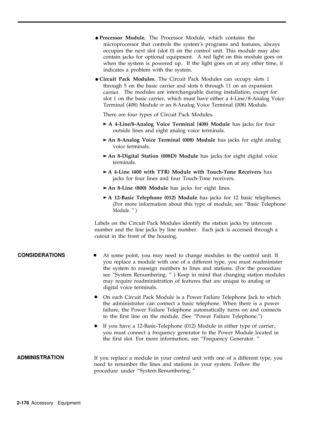
Control Unit Modules
Only 82 responding stations
Line/8-Analog Voice Terminal 408 Module has jacks for four
Line 400 with TTR Module with Touch-Tone Receivers has
Frequency Generator
See Figure
General Purpose Adapter
Using Join Mode
Using Basic Mode
Cordless telephones. An example is shown in Figure
Hands-Free Unit
Using Auto Mode
Speakerphone Light Volume control Microphone
Touch Microphone
When you are ready to speak again with the person
Touch Speakerphone
Touch Microphone again
Dial the outside number
Headset and Headset Adapter
Allows you to handle calls more easily. See Figure
These protectors must be mounted indoors
In-Range, Out-of-Building Voice Termianl and Protectors
Is located
Your Irob protectors
Loudspeaker Paging System
Music Coupler
Outside calls
Power Failure Telephones
Different line modules
Supplemental Alert Adapter
186MERLIN II System Features
Administration Mode
Enter and Leave
Basic Administration Procedures
Administration Procedure Do This
Touch #
Attendant console position
Touch Auto Intercom buttons
Music-on-Hold jack
Dial #302 Touch line buttons
Touch-Tone or rotary signaling
Voice Terminal Type Setting raised plastic
Voice Announcement to Busy Voice
To assign lines and line pools to voice
To assign Dial Access to Line Pools to
Dial pool code
= none
Optional Systemwide Features
Touch Drop Touch Message
Touch the fixed button Conference, Transfer, or Drop
Dial number of Call Pickup group 01 through
Call Report To set time and date and administer
Call Pickup Groups To assign voice terminals to groups
To get a printout of Call Report
Do This Touch Speaker
Steady green on = all calls permitted unrestricted
Touch Conference twice
Do This Touch Message
Groups Dial #906 and wait for beep
To associate lines with groups for
To get a printout of Call Distribution
Group Paging To assign voice terminals to groups for
Creating a password Dial # Dial a 4-digit password
Night Service, Enhanced To assign voice terminals to
To set up Outward Restriction by
To set up an allowed list of emergency
Default Dial #
To suspend Night Service with
Service Information Dial #907 and wait for beep
To record current day for Night
Reminder Service Cancel
Recall Timer
Dial number to specify timer interval
To get a printout of Reminder Service
Transfer Return Interval
Dial #306
Administration Button Codes
18Administration Button Codes
Set the Camp On return interval
20Administration Button Codes
Menu-Driven Administration Procedures
Menu-Driven Administration Map
Menu-Driven Administration Map
Behind switch system, touch More , BehindSw
For a
24Menu-Driven Administration Procedures
Attendant Position Setting
Voice terminal line/line pool assignments
Reach screen via More , Tables , ARS-6dgt
28Menu-Driven Administration Procedures
Menu-Driven Administration Procedures3-29
30Menu-Driven Administration Procedures
Menu-Driven Admlnlstration Procedures
Inward only
Reach screen via Lines, Disa
Touch NoRestr for no restriction, or touch InwdOnly for
To put consoles into ESS Display
34Menu-Driven Administration Procedures
Dial Touch Conference to return to the administration menu
Touch Drop
Dial * if it is a marked
Dial number
Voice Terminal Features and Programming Codes
Voice Terminal Features
Voice Terminal Features and Programming Codes
Call Reporting
Privacy
42Voice Terminal Features and Programming Codes
Voice Terminal Status
Programming Codes Other Numbers Feature
Voice Terminal Programming Codes
Auto Answer-All
46Voice Terminal Features and Programming Codes
Index
2Index
Index I
4Index