Cisco ONS 15216 EDFA2 Operations Guide
Corporate Headquarters
Cisco ONS 15216 EDFA2 Operations Guide
N T E N T S
Rack Installation and Power Supply Connection Procedures
Srom cfg ip modify Command
Snmp mib get Command Snmp mib list Command
Provisioning Using TL1
Introduction
Status Information Needed by Cisco TAC
Cisco ONS 15216 EDFA2 Temperature Requirement A-25
Eye Damage Warning
Xii
G U R E S
Xiv
Gain Range
TL1 Commands and Messages Security Permissions Access Levels
Table A-1
Xviii
Obtaining Documentation
Cisco.com
Optical Networking Product Documentation CD-ROM
Ordering Documentation
Obtaining Technical Assistance
Documentation Feedback
Cisco TAC Escalation Center
Technical Assistance Center
Cisco TAC Website
Obtaining Additional Publications and Information
Wavelength Protection Switching
Bandwidth On Demand
Key Features
Wavelength Protection Switching
Constant Gain
Gain Flattening
Transient Suppression
Low Noise
Snmp MIBs
6 TL1
Optical Specifications
Requirement Specification
There is no input power, the ONS 15216 EDFA2 has
DBm of output power. For additional safety
Channel Loading
Maximum Input Power
Maximum Channel Power
Electrical Specifications
ONS 15216 EDFA2 Electrical Specifications
Mechanical Specifications
External Features
4lists the ONS 15216 EDFA2 mechanical specifications
TR-NWT-000332, Issue 4, Method
ONS 15216 EDFA2 Dimensions
Front Panel
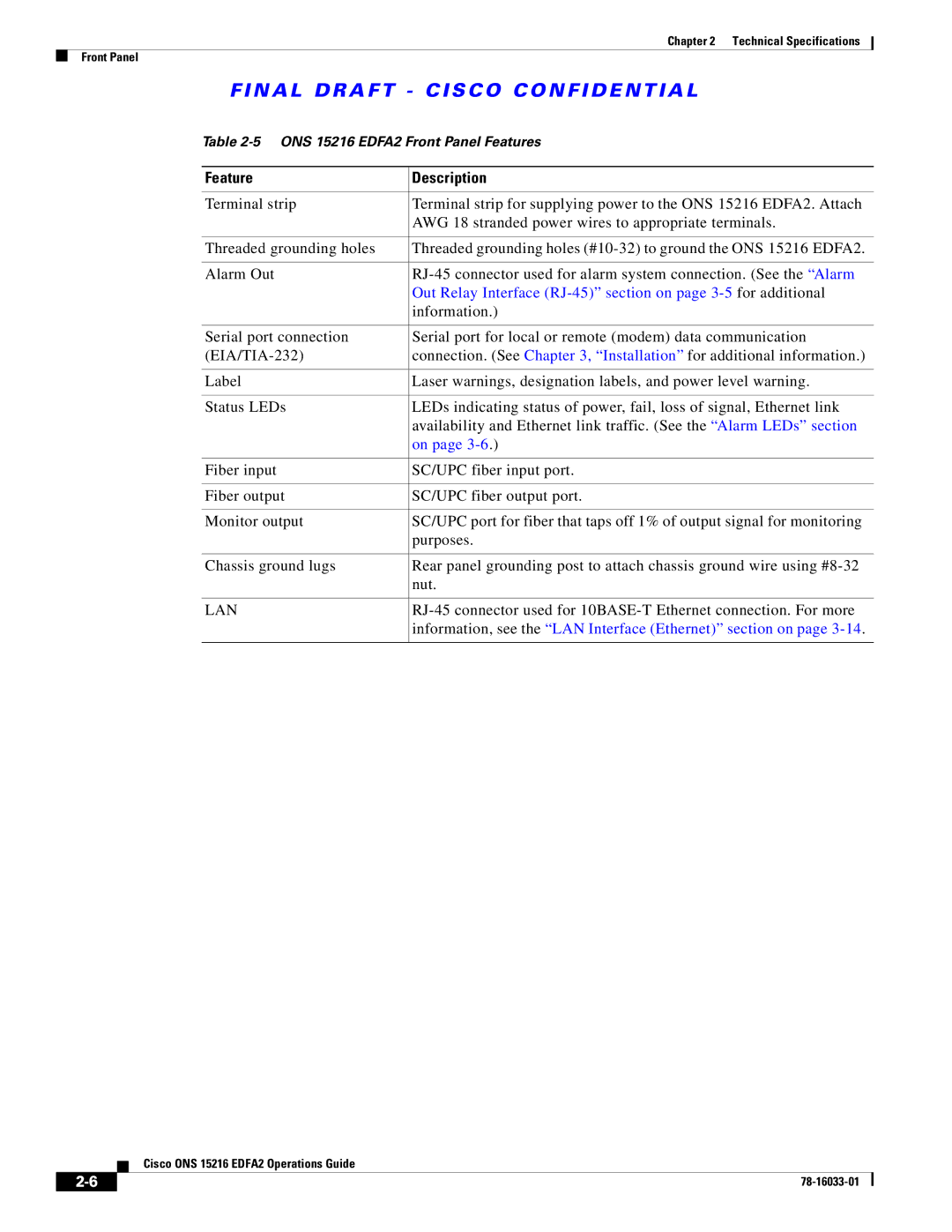
Feature Description
ONS 15216 EDFA2 Front Panel Features
Information
LAN
Standard Precautions
Placement and Power Connection
Introduction
General Rack Considerations
Rack Installation and Power Supply Connection Procedures
SC/UPC Optical Ports
Safety Requirements
Optical Connection Procedure
Gain Range
Optical Amplification Operation Verification Procedure
Gain Total Input Power dBm Total Output Power dBm
Alarm Out Relay Interface RJ-45
Alarm Relay Connection Procedure
Communications
Relay Pinout Description
Alarm LEDs
Power LED Green
Power Fail LOS
Fail LED Red
Serial Connection Procedure
Serial Interface EIA/TIA-232 Communication
LOS LED Yellow
Ethernet Socket LEDs
HyperTerminal Connect To Dialog Box
Click Settings -5 on page 3-10 and click Ascii Setup
Optical Amplifier Properties Dialog Box Settings Tab
Serial Interface Remote Communication via Modem
Remote Communication Component Requirements
Component
Communication Component List
Modem Signals
Modem Power Up
Modem Configuration Settings
Up U or Down D Description
Setting and Saving Modem Settings
Modem Setting Description
LAN Interface Ethernet
PC Connection via Modem
LAN Connection Procedure
N a L D R a F T C I S C O C O N F I D E N T I a L
Provisioning Using ASH and Snmp
Following sections describe these steps in detail
Then enter the following command at the hostname prompt
Example 4-1 ASH Shell Login Window
Example 4-2 ASH Shell Login Response
SidtidnameONS15216 EDFA2 ED-NE-GEN123CLI=ASH
Log In via LAN Port Using Telnet Optional
Set IP Address
Set Power Bus Mode Simplex or Duplex
Set Date and Time
Verify Amplifier Operational Status
You are now connected to the ONS 15216 EDFA2 via Telnet
Set Gain
Set Alarm Thresholds
Example 4-7 Setting the Gain
Example 4-8 Displaying the Alarm Thresholds
Class CERENT-15216-EDFA-MIB.cerent15216EdfaCfgGroup =
Alarm Threshold Attribute Definitions
N a L D R a F T C I S C O C O N F I D E N T I a L
N a L D R a F T C I S C O C O N F I D E N T I a L
Set Password
Example 4-9 Changing Current User’s Password
Add Users
Save Changes
Example 4-10 Adding a New User
Example 4-11 Saving Changes
Back Up System Configuration
Log Off
System responds with progress information
Example 4-12 Logging Off
Save the changes
Restore System Configuration
Reboot the ONS 15216 EDFA2
Recover Default Password
At the hostname prompt, enter the following command
Snmp Overview
Snmp Components
ONS 15216 EDFA2 Snmp Elements
Snmp Agent
Snmp MIB
Snmp manager Snmp elements are shown in Figure
Snmp Manager
Snmp MIBs and Message Types
Snmp MIB
Command Syntax Using the Snmp Agent
Example 5-1 snmp Command Followed by the Tab Key
Operation Description
Snmp Operation Types
Default Community Strings
Community String Default Privileges
Example 5-2 snmp table display Command
Command
Creating a View
Set View Entry
Snmp row set local cerent15216EdfaViewEntry
Data Prompt Command Description
Creating a Community Entry
Set CommunityEntry
Snmp row set local cerent15216EdfaCommunityEntry
Creating a Community Entry
4displays the definitions for the community entry values
Data Prompt Description
Example 5-5 cerent15216EdfaCommunityEntry Display Command
Display CommunityEntry
Snmp row display local cerent15216EdfaCommunityEntry
Snmp Operation Decimal Values
Setup for CTM Access
Tables and Groups
Cerent15216EdfaCfgGroup Variable Descriptions
Maximum Variable Syntax Access Description
CfgGroup Table
N a L D R a F T C I S C O C O N F I D E N T I a L
Cerent15216EdfaPumpCfgEntry Variable Descriptions
Changing the Pump Control Mode
PumpCfgEntry Table
Changing the Pump Control Value
200
Example 5-7 Changing Value for Constant Pump Current Mode
OverallStatusGroup Table
Cerent15216EdfaOverallStatusGroup Variable Descriptions
OverallControl Table
PumpStatusEntry Table
Cerent15216EdfaOverallControl Variable Descriptions
10 cerent15216EdfaPumpStatusEntry Variable Descriptions
AlarmEntry Table
11 cerent15216EdfaAlarmEntry Variable Descriptions
OpGroup Table
12 cerent15216EdfaOpGroup Variable Descriptions
13 cerent15216EdfaVersionGroup Variable Descriptions
Setting Up Traps
VersionGroup Table
Display Trap Command
Notification MIB Items Description
Snmp table display local cerent15216EdfaCommTrapEntry
Displays the communities for traps. See Example
Set Trap Command
Set Agent Trap Enable
Snmp attribute set local cerent15216EdfaAgentTrapEnable
Example 5-9 cerent15216EdfaCommTrapEntry Set Command
Get Agent Trap Enable
Snmp attribute get local cerent15216EdfaAgentTrapEnable
Retrieving Information
IP Address
16describes the attributes displayed by these commands
Date and Time
Attribute Description
Snmp attribute get local cerent15216EdfaRtcDateAndTime
Example 5-12 cerent15216EdfaOverallControl Display Command
Power Gain
16 cerent15216EdfaRtcDateAndTime Command Attributes
Case Temperature
Case Temperature Value
Case Temperature Alarm Threshold
Example 5-13 cerent15216EdfaPumpStatusEntry Display Command
Case Temperature Alarm Hysteresis
Example 5-14 cerent15216EdfaCfgGroup Display Command
Snmp attribute get local cerent15216EdfaCtmpMax
Snmp attribute get local cerent15216EdfaCtmpMaxHysteresis
Power Bus Alarm Threshold
Power Bus
Power Bus Mode
Input Power Signal
Input Power Signal Value
Snmp attribute get local cerent15216EdfaInPoweruW
Snmp attribute get local cerent15216EdfaInPowerdBm
Output Power
Loss of Signal Input Power Alarm Threshold
Loss of Signal Input Power Alarm Hysteresis
Output Power Value
Loss of Output Power Alarm Setpoint
Displays output power value in milliwatts
Snmp attribute get local cerent15216EdfaOutPowerdBm
Snmp attribute get local cerent15216EdfaLpoutSetpoint
Example 5-15 cerent15216EdfaLpoutDeviation Set Command
Snmp attribute get local cerent15216EdfaLpoutDeviation
Snmp attribute get local cerent15216EdfaLpoutHysteresis
Database Backup and Restore
Loss of Output Power Alarm Hysteresis
Database Backup Procedure
Database Restore Procedure
Example 5-16 cerent15216EdfaAlarmEntry Display Command
Alarm Entry
Snmp table display local cerent15216EdfaAlarmEntry
Summary of Snmp Alarms
17summarizes the ONS 15216 EDFA2 Snmp alarms
Alarm Index Alarm ID Description Priority
17 Snmp Alarms
N a L D R a F T C I S C O C O N F I D E N T I a L
User Access Levels
Command Description
ASH Commands Security Permissions Access Levels
Clear Clears the shell screen Yes
Gain gain modify Modifies gain setting Yes
Help Gives help about commands Yes
Login Allows the user to log into shell Yes
History Displays the history list Yes
Restore system Restores configuration from backup file Yes
Shell more disable Disables more Yes
Shell more enable Enables more Yes
Network host ftp FTPs to remote host Yes
Snmp attribute set Sets an attribute Yes
Snmp mib get Gets a MIB Yes
Snmp mib list Lists a MIB Yes
Snmp row get Gets a row Yes
Srom cfg ip modify Modifies the serial ROM IP contents Yes
User entry create Creates a new user Yes
User entry delete Deletes the user Yes
User entry edit Edits an existing user entry Yes
Configuration Commands
Srom cfg boot display Command
Srom cfg boot display
Syntax Description srom cfg boot display
Srom cfg boot modify Command
Srom cfg ip display Command
Srom cfg boot modify
Syntax Description srom cfg boot modify
Srom cfg ip modify Command
Pdm busmode display Command
Srom cfg ip modify
Pdm busmode display
Pdm busmode modify Command
Pdm cfg threshold bus display Command
Pdm cfg threshold bus modify Command
Gain gain display Command
Administrative Commands
Gain gain modify Command
Voa power input display Command
Syntax Description
Clear Command
Exit Command
Help Command
History Command
Processor reset Command
Shell Commands
Login and logoff Commands
Shell lines set Command
Shell more enable and disable Commands
Shell status display Command
Shell type modify Command
Flash File System Commands
Ffs file list Command
Example 6-12 ffs file list Command
Syntax Description shell type modify tl1 ash
Snmp Commands
Snmp attribute get Command
Accesses and displays a specific MIB attribute. See Example
Example 6-13 snmp attribute get Command
Snmp attribute list Command
Example 6-14 snmp attribute get Command List
Example 6-15 snmp attribute list Command
Snmp attribute list
Snmp attribute set Command
Snmp mib display Command
Snmp attribute set
Snmp mib display
Snmp mib get Command
Snmp mib list Command
Snmp mib get
Syntax Description snmp mib get IPaddress local
Example 6-19 snmp row display Command
Snmp row display
Snmp row get Command
Snmp row set Command
Snmp row get
Snmp row set
Snmp subtree display Command
Snmp subtree get Command
Snmp subtree list Command
Example 6-24 snmp subtree list Command
Snmp subtree list
Syntax Description snmp subtree list IPaddress local
Snmp table display Command
Example 6-25 snmp table display Command
Snmp table display
Snmp table display IPaddress local
Snmp table get Command
Snmp table list Command
Snmp table get
Syntax Description snmp table get IPaddress local table
User Commands
Snmp tree attribute list Command
Example 6-28 snmp tree attribute list Command
Snmp tree attribute list
User entry create Command
User entry edit Command
Syntax Description user entry create name usermode
Syntax Description user entry edit username
User entry delete Command
User file display and user name display Commands
User entry delete
Syntax Description user entry delete username
User inactivity modify and user inactivity display Commands
User passwd set Command
Command to display the current inactivity values
User inactivity modify or user inactivity display
User active list Command
User active message send Command
Manufacturing Information Access Commands
Snmp table display local entPhysicalEntry Command
Snmp table display local entPhysicalEntry
Displays the entity information. See Example
Restore Commands
Backup system Command
Restore system Command
Syntax Description backup system filename
Manufacturer restore defaults all Command
Manufacturer Mode
Manufacturer restore defaults passwords Command
FTP Command Line
To start an FTP session, use the following command
When prompted, enter the FTP user password as shown
Example of FTP from a Remote Server
Ftp type
At the ftp prompt, enter the following command
Example of FTP to a Remote Server
FTP Commands
Example 7-1 FTP Help Command
N a L D R a F T C I S C O C O N F I D E N T I a L
Provisioning Using TL1
Then enter the following command at the ASH hostname prompt
Example 8-1 TL1 Shell Login Prompt
Example 8-2 TL1 Shell Login Response
SidtidnameONS15216 EDFA2 ACT-USERCISCO15100
255.0,DEFRTR=192.167.3.20
SidtidnameONS15216 EDFA2 INIT-SYSALL1021
Example 8-6displays sample output of this command
Example 8-4 Setting the Date and Time Using TL1
Example 8-5 Setting the Power Bus Mode Using TL1
Pwrbusmode value can be Simplex or DUPLEX. See Example
Example 8-7 Setting the Gain Using TL1
SidtidnameONS15216 EDFA2 ED-DWDMALL123OVERALLGAIN=200
Example 8-8shows sample command outputs
Example 8-8 Displaying the Alarm Thresholds Using TL1
SidtidnameONS15216 EDFA2 RTRV-TH-DWDMALL124
SidtidnameONS15216 EDFA2 RTRV-TH-EQPTALL125
Losth
Loshyst
Lpoutdev
Lpouthyst
Lpoutsetpt
Minctmp
Maxctmp
Maxctmphyst
SidtidnameONS15216 EDFA2 ED-PIDCISCO15130OLDPW,NEWPW
Example 8-9 Changing Current User’s Password Using TL1
Minctmphyst
Example 8-10 Adding a New User Using TL1
Example 8-11 Logging Off Using TL1
SidtidnameONS15216 EDFA2 ENT-USER-SECUjsmith140jspasswd,,RW
SidtidnameONS15216 EDFA2 CANC-USERCISCO15150
SidtidnameONS15216 EDFA2 INIT-SYSALL1241
Source Identifier sid and Target Identifier tid
Explanation of Command Parameters
Connection to the ONS 15216 EDFA2
Command Code Modifier ccm
Access Identifier aid
Notation
Correlation Tag ctag
Summary of Autonomous Alarms and Messages
Symbol Meaning Description
Rept EVT Eqpt Cutoverreset
Rept EVT Dwdm CTRLMODE1
Rept EVT Dwdm CTRLMODE2
Rept EVT Dwdm Gainchgd
Software Reset
On page 9-5summarizes the ONS 15216 EDFA2 clear alarms
New Software Load
File Transfer
ACT-USER
ALW-MSG-ALL
Apply
CANC-USER
Rept ALM Dwdm
Rept ALM ENV
Rept EVT Dwdm
Rept EVT ENV
RTRV-ENV
RTRV-HDR
RTRV-INV
RTRV-NE-GEN
TL1 Commands and Autonomous Messages
CommandACT-USER
ACT-USER
ALW-MSG-ALL
Powerbusa
Powerbusb
Softwarereset
CommandAPPLY
Apply
Softwareload
CommandCANC-USER
CommandCOPY-RFILE
CANC-USER
COPY-RFILE
Ftp//useridpassword@ftphostport/urlp
Ath
File//localhost/urlpath
Cwd1/cwd2/…/cwdn/filename
CommandCPY-MEM
CPY-MEM
CFG
LOG
CommandDLT-RFILE
DLT-RFILE
Dbcfg
MEM
CommandDLT-USER-SECU
CommandED-DAT
DLT-USER-SECU
ED-DAT
CommandED-DWDM
ED-DWDM
CommandED-ENV
ED-ENV
Aid
PWR-A, PWR-B, and ALL have same input effect
CommandED-NE-GEN
ED-NE-GEN
CommandED-PID
ED-PID
TL1
ASH
CommandED-USER-SECU
CommandENT-USER-SECU
ED-USER-SECU
ENT-USER-SECU
Permissions
CommandINH-MSG-ALL
INH-MSG-ALL
LOS
Gainchgd
CommandINIT-SYS
INIT-SYS
Rept ALM Dwdm
Eqpt ALL
Gain Out of Range alarm cerent15216EdfaAlarmGain
Loss of Output Power alarm cerent15216EdfaAlarmLpout
Non-service affecting
25 Rept ALM Dwdm Syntax Description
Rept ALM ENV
Date Yyyy-mm-dd Date of origination of TL1 message
Example 9-21 Rept ALM ENV Message
26 Rept ALM ENV Syntax Description
Rept ALM Eqpt
Example 9-22 Rept ALM Eqpt Message
27 Rept ALM Eqpt Syntax Description
Affecting optical signal or power bus
General parameters of the ONS 15216 EDFA2 not directly
Reports autonomous events. Reports when an event is logged
Rept EVT Dwdm / Rept EVT ENV / Rept EVT Eqpt
Time Hhmmss Time of origination of TL1 message
Rept EVT Dwdm or Rept EVT ENV or Rept EVT Eqpt
EVN
Eqpt Softwarereset
Rept EVT Fxfr
CommandRTRV-ALM-ALL
RTRV-ALM-ALL
Example 9-25 RTRV-ALM-ALL Command and Response
Dwdm Lpout
Dwdm Ctmp
30 RTRV-ALM-ALL Syntax Description
CommandRTRV-ALM-DWDM
Generates a report on active Dwdm alarms
Example 9-26 RTRV-ALM-DWDM Command and Response
RTRV-ALM-DWDM
31 RTRV-ALM-DWDM Syntax Description
CommandRTRV-ALM-ENV
Example 9-27 RTRV-ALM-ENV Command and Response
RTRV-ALM-ENV
32 RTRV-ALM-ENV Syntax Description
CommandRTRV-ALM-EQPT
Example 9-28 RTRV-ALM-EQPT Command and Response
RTRV-ALM-EQPT
Aid Eqpt and ALL have same input effect
Ctmp
CommandRTRV-AO
RTRV-AO
ALM
EVT
CommandRTRV-COND-ALL
Example 9-30 RTRV-COND-ALL Command and Response
RTRV-COND-ALL
35 RTRV-COND-ALL Syntax Description
LOS
CommandRTRV-COND-DWDM
Generates a report on the condition state of Dwdm alarms
Example 9-31 RTRV-COND-DWDM Command and Response
RTRV-COND-DWDM
CommandRTRV-COND-ENV
Example 9-32 RTRV-COND-ENV Command and Response
RTRV-COND-ENV
Amp01ONS15216 EDFA2 RTRV-COND-ENVAmp01ALL229PWRBUSA
37 RTRV-COND-ENV Syntax Description
CommandRTRV-COND-EQPT
Generates a report on the condition state of general alarms
Example 9-33 RTRV-COND-EQPT Command and Response
RTRV-COND-EQPT
CommandRTRV-DFLT-SECU
Retrieves the timeout values for user access levels
Example 9-34 RTRV-DFLT-SECU Command and Response
RTRV-DFLT-SECU
Timeout Integer Timeout in minutes
CommandRTRV-DWDM
Retrieves the ONS 15216 EDFA2 optical control configuration
RTRV-DWDM
40 RTRV-DWDM Syntax Description
ConstOutputPower. a valid mode only for pump
Idle
Overallgain
CommandRTRV-ENV
RTRV-ENV
CommandRTRV-HDR
CommandRTRV-INV
RTRV-HDR
RTRV-INV
43 RTRV-INV Syntax Description
CommandRTRV-NE-GEN
RTRV-NE-GEN
Example 9-39 RTRV-NE-GEN Command and Response
Aid Always Eqpt
44 RTRV-NE-GEN Syntax Description
Amp01ONS15216 EDFA2 RTRV-NE-GENAmp01123
CommandRTRV-RFILE
Example 9-40 RTRV-RFILE Command and Response List all Files
RTRV-RFILE
45 RTRV-RFILE Syntax Description
CommandRTRV-TH-DWDM
Example 9-42 RTRV-TH-DWDM Command and Response
RTRV-TH-DWDM
46 RTRV-TH-DWDM Syntax Description
CommandRTRV-TH-ENV
RTRV-TH-ENV
CommandRTRV-TH-EQPT
RTRV-TH-EQPT
Pwrbusmin
Pwrbusmax
Maximum case temperature cerent15216EdfaCtmpMax
Thresholdvalue can be between 20 and 70, with default of 65
Maximum case temperature hysteresis
Thresholdvalue can be between 0 and 10, with default of 1,
CommandRTRV-TOD
RTRV-TOD
CommandRTRV-USER-SECU
CommandSET-ATTR-SECUDFLT
RTRV-USER-SECU
SET-ATTR-SECUDFLT
9-6 for access level permissions
CommandSET-TH-DWDM
SET-TH-DWDM
Sets optical threshold values for the ONS 15216 EDFA2
CommandSET-TH-ENV
SET-TH-ENV
CommandSET-TH-EQPT
SET-TH-EQPT
Thresholdvalue can be between 20 and 70, with default
CommandSTA-LOCL-RST
Example 9-51 STA-LOCL-RST Command
STA-LOCL-RST
Troubleshooting
Front panel of the ONS 15216 EDFA2 has five LEDs
Alarm Indicators
LEDs and Office Alarms
10-3
Optical Alarms
LOS Loss of Signal Alarm
Gain Gain Out of Range Alarm
LOS Gain Lpout
Lpout Loss of Output Power Alarm
Equipment Alarms
Ctmp Case Temperature Out of Range Alarm
LCRNT1 and LCRNT2 Excessive Pump Current Alarms
LTMP1 and LTMP2 Excessive Pump Temperature Alarms
Troubleshooting Typical Scenarios
Environmental Alarms
No Output Power after Adjusting Gain Settings
Pwrbusa and Pwrbusb Power Bus Alarms
Image File Download Incomplete
10.2.2 2.0.1 to 2.2.1 Upgrade Attempt
Boot Up Failure
Hostnameedfaboot% ffs file list
Hostnameedfaboot% srom cfg boot display
No Response from RS-232 Port
No Response from LAN Port
Lost Password
Status Information Needed by Cisco TAC
10-12
Regulatory Compliance
Discipline Standard Description
EMC
ACA AS/NZS3548
Translated Safety Warnings
Safety warnings contained in this document are
N a L D R a F T C I S C O C O N F I D E N T I a L
N a L D R a F T C I S C O C O N F I D E N T I a L
DC Power Supply Warning
Installation Warning
Power Cord Warning
No On/Off Switch Warning
Selv Circuit Warning
Laser Radiation Warning
Power Cabling Warning
Laser Beam Warning
Grounded Equipment Warning
Ground Connection Warning
Jewelry Removal Warning
Qualified Personnel Warning
Supply Circuit Warning
Power Supply Wiring Warning
Invisible Laser Radiation Warning
Incorrect Connection Warning
Ground Conductor Warning
Voltages on DC-input Power Supply Terminals
More Than One Power Supply
Cisco ONS 15216 EDFA2 Rack Installation
Exposed DC Power Wire Warning
VDC Power System
Chassis Power Connection
Cisco ONS 15216 EDFA2 Temperature Requirement
N a L D R a F T C I S C O C O N F I D E N T I a L
Cisco ONS 15216 EDFA2 Power Circuit Overload Warning
Product Disposal Warning
Energy Hazard
Unit Grounding Protection Warning
DC Power Disconnection Warning
Ground Wire Warning
N a L D R a F T C I S C O C O N F I D E N T I a L
N a L D R a F T C I S C O C O N F I D E N T I a L
Class B EMC Warning Safety Requirements Warning
Laser Radiation Warning
Fiber Disconnect Sequence Warning
Optical Connector Warning
Optical Connector Disconnect Warning
Eye Damage Warning
Static Electricity Warning
Connector Cleaning Warning
Cable Connection Sequence Warning
Module Removal Warning
DC Power Selv Requirement Warning
Reinforced Insulation Warning
Power Supply Voltage Warning
DC Power Supply Connection Warning
N a L D R a F T C I S C O C O N F I D E N T I a L
N a L D R a F T C I S C O C O N F I D E N T I a L
ASH TL1 ACT-USER
Snmp
Electrical specifications EntPhysicalEntry
Flash file system commands
Front panel LEDs FTP commands
Ctag
Maxctmp Maxctmphyst mechanical specifications 2-4MIBs
Default recovery Pdm busmode display Pdm busmode modify
Remote communications
Rept ALM Dwdm Rept ALM ENV Rept ALM Eqpt Rept EVT Dwdm
SET-TH-ENV SET-TH-EQPT
MIB
User active list User active message send 6-29user commands
STA-LOCL-RST
IN-7
IN-8