C8051F340/1/2/3/4/5/6/7
22.2.1. Edge-triggered Capture Mode
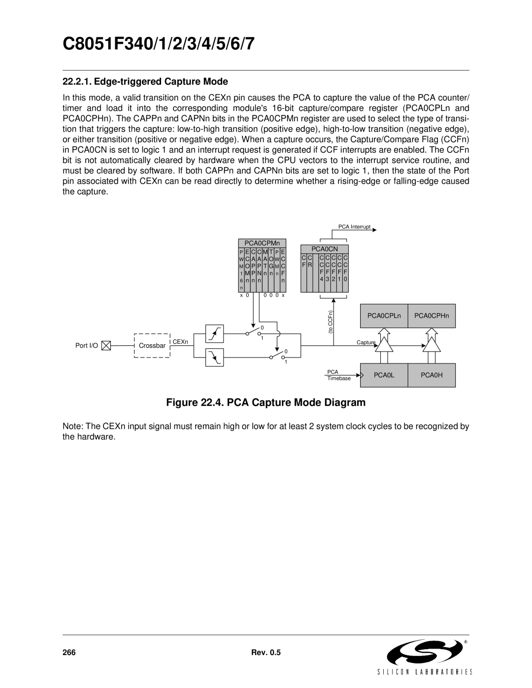
In this mode, a valid transition on the CEXn pin causes the PCA to capture the value of the PCA counter/ timer and load it into the corresponding module's
PCA0CPMn
PCA Interrupt
Port I/O ![]() Crossbar
Crossbar
CEXn
PE C C M T P E W C A A A O W C M O P P T G M C 1 M P N n n n F
6 | n n n |
| n | ||
n |
|
|
|
|
|
x 0 |
|
| 0 0 0 x | ||
|
|
|
|
|
|
|
|
|
|
|
|
0
1
0
1
PCA0CN
C C C C C C C F R C C C C C F F F F F 4 3 2 1 0
CCFn)(to
PCA0CPLn PCA0CPHn
Capture
PCA | PCA0L | PCA0H | |
Timebase | |||
|
|
Figure 22.4. PCA Capture Mode Diagram
Note: The CEXn input signal must remain high or low for at least 2 system clock cycles to be recognized by the hardware.
266 | Rev. 0.5 |