C8051F340/1/2/3/4/5/6/7
14.1. Programmable Internal High-Frequency (H-F) Oscillator
All C8051F340/1/2/3/4/5/6/7 devices include a programmable internal oscillator that defaults as the system clock after a system reset. The internal oscillator period can be programmed via the OSCICL register shown in SFR Definition 14.2. The OSCICL register is factory calibrated to obtain a 12 MHz internal oscil- lator frequency. Electrical specifications for the precision internal oscillator are given in Table 14.1 on page 145. Note that the system clock may be derived from the programmed internal oscillator divided by 1, 2, 4, or 8, as defined by the IFCN bits in register OSCICN. The divide value defaults to 8 following a reset.
14.1.1. Internal H-F Oscillator Suspend Mode
The internal
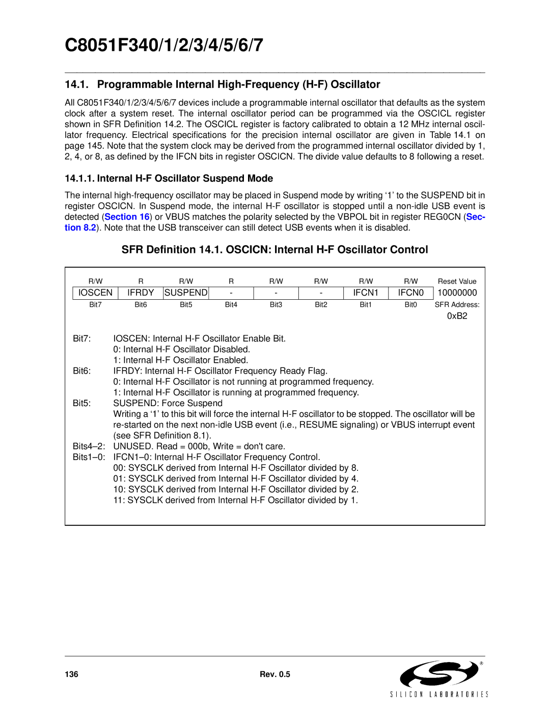
SFR Definition 14.1. OSCICN: Internal H-F Oscillator Control
| R/W |
| R | R/W | R | R/W | R/W | R/W | R/W | Reset Value | |
| IOSCEN |
| IFRDY | SUSPEND |
| - | - | - | IFCN1 | IFCN0 | 10000000 |
| Bit7 |
| Bit6 | Bit5 | Bit4 | Bit3 | Bit2 | Bit1 | Bit0 | SFR Address: | |
|
|
|
|
|
|
|
|
|
|
| 0xB2 |
| Bit7: | IOSCEN: Internal |
|
|
|
| |||||
|
| 0: Internal |
|
|
|
|
| ||||
|
| 1: Internal |
|
|
|
|
| ||||
| Bit6: | IFRDY: Internal |
|
|
| ||||||
|
| 0: Internal |
|
| |||||||
|
| 1: Internal |
|
| |||||||
| Bit5: | SUSPEND: Force Suspend |
|
|
|
|
|
| |||
|
| Writing a ‘1’ to this bit will force the internal | |||||||||
|
| ||||||||||
|
| (see SFR Definition 8.1). |
|
|
|
|
|
| |||
| UNUSED. Read = 000b, Write = don't care. |
|
|
|
| ||||||
|
|
|
| ||||||||
|
| 00: SYSCLK derived from Internal |
|
| |||||||
|
| 01: SYSCLK derived from Internal |
|
| |||||||
|
| 10: SYSCLK derived from Internal |
|
| |||||||
|
| 11: SYSCLK derived from Internal |
|
| |||||||
|
|
|
|
|
|
|
|
|
|
|
|
136 | Rev. 0.5 |