C8051F340/1/2/3/4/5/6/7

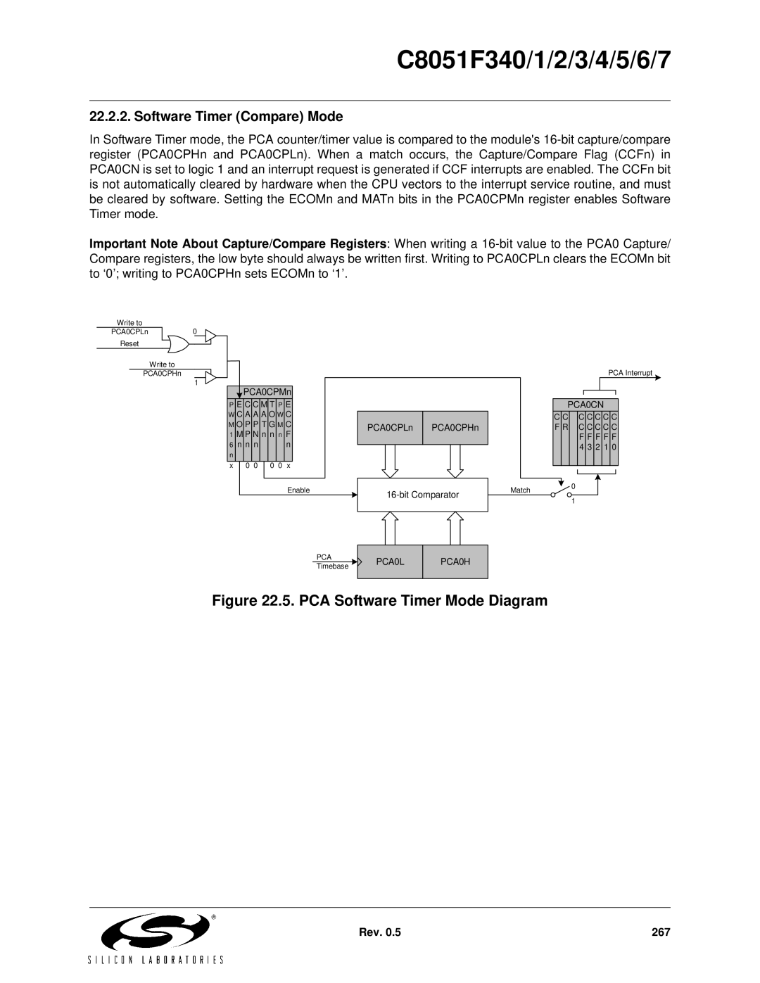
22.2.2. Software Timer (Compare) Mode

In Software Timer mode, the PCA counter/timer value is compared to the module's 16-bit capture/compare register (PCA0CPHn and PCA0CPLn). When a match occurs, the Capture/Compare Flag (CCFn) in PCA0CN is set to logic 1 and an interrupt request is generated if CCF interrupts are enabled. The CCFn bit is not automatically cleared by hardware when the CPU vectors to the interrupt service routine, and must be cleared by software. Setting the ECOMn and MATn bits in the PCA0CPMn register enables Software Timer mode.

Important Note About Capture/Compare Registers: When writing a 16-bit value to the PCA0 Capture/ Compare registers, the low byte should always be written first. Writing to PCA0CPLn clears the ECOMn bit to ‘0’; writing to PCA0CPHn sets ECOMn to ‘1’.

Write to

PCA0CPLn0

ENB

Reset

Write to

PCA0CPHn ENB

1

PCA0CPMn

P E C C M T P E W C A A A O W C M O P P T G M C 1 M P N n n n F

6 n n n n n

x

0 0

0 0 x


Enable

PCA0CPLn PCA0CPHn

16-bit Comparator

PCA Interrupt

PCA0CN

C

C


C

C

C

C

C

F

R


C

C

C

C

C


F

F

F

F

F


4

3

2

1

0


Match0

1

PCA

Timebase

PCA0L

PCA0H

Figure 22.5. PCA Software Timer Mode Diagram

Rev. 0.5

267

Page 267
Image 267
Silicon Laboratories C8051F343, C8051F347, C8051F346, C8051F341 PCA Software Timer Mode Diagram, Software Timer Compare Mode