C8051F340/1/2/3/4/5/6/7
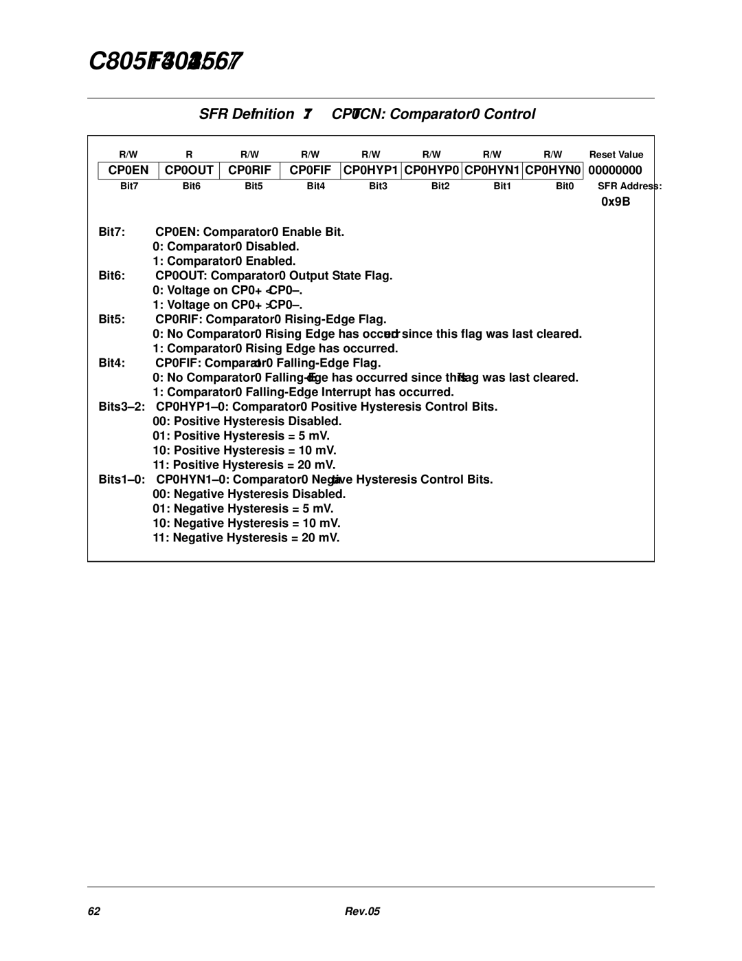
SFR Definition 7.1. CPT0CN: Comparator0 Control
R/W |
| R | R/W | R/W | R/W | R/W | R/W | R/W | Reset Value | ||
CP0EN |
| CP0OUT | CP0RIF |
| CP0FIF | CP0HYP1 | CP0HYP0 | CP0HYN1 | CP0HYN0 | 00000000 | |
Bit7 |
| Bit6 | Bit5 | Bit4 | Bit3 | Bit2 | Bit1 | Bit0 | SFR Address: | ||
|
|
|
|
|
|
|
|
|
|
| 0x9B |
Bit7: | CP0EN: Comparator0 Enable Bit. |
|
|
|
|
|
| ||||
| 0: Comparator0 Disabled. |
|
|
|
|
|
| ||||
| 1: Comparator0 Enabled. |
|
|
|
|
|
|
| |||
Bit6: | CP0OUT: Comparator0 Output State Flag. |
|
|
|
|
| |||||
| 0: Voltage on CP0+ < |
|
|
|
|
|
| ||||
| 1: Voltage on CP0+ > |
|
|
|
|
|
| ||||
Bit5: | CP0RIF: Comparator0 |
|
|
|
|
| |||||
| 0: No Comparator0 Rising Edge has occurred since this flag was last cleared. |
| |||||||||
| 1: Comparator0 Rising Edge has occurred. |
|
|
|
|
| |||||
Bit4: | CP0FIF: Comparator0 |
|
|
|
|
| |||||
| 0: No Comparator0 |
| |||||||||
| 1: Comparator0 |
|
|
| |||||||
|
|
| |||||||||
| 00: Positive Hysteresis Disabled. |
|
|
|
|
|
| ||||
| 01: Positive Hysteresis = 5 mV. |
|
|
|
|
|
| ||||
| 10: Positive Hysteresis = 10 mV. |
|
|
|
|
|
| ||||
| 11: Positive Hysteresis = 20 mV. |
|
|
|
|
|
| ||||
|
|
| |||||||||
| 00: Negative Hysteresis Disabled. |
|
|
|
|
|
| ||||
01: Negative Hysteresis = 5 mV.
10: Negative Hysteresis = 10 mV.
11: Negative Hysteresis = 20 mV.
62 | Rev. 0.5 |