C8051F340/1/2/3/4/5/6/7
17.5.4. Slave Transmitter Mode
Serial data is transmitted on SDA and the clock is received on SCL. When slave events are enabled (INH
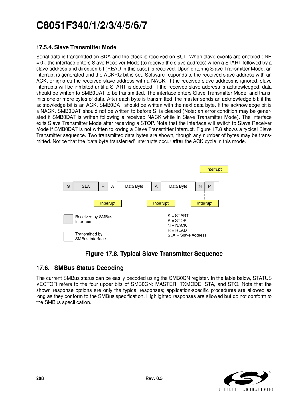
=0), the interface enters Slave Receiver Mode (to receive the slave address) when a START followed by a slave address and direction bit (READ in this case) is received. Upon entering Slave Transmitter Mode, an interrupt is generated and the ACKRQ bit is set. Software responds to the received slave address with an ACK, or ignores the received slave address with a NACK. If the received slave address is ignored, slave interrupts will be inhibited until a START is detected. If the received slave address is acknowledged, data should be written to SMB0DAT to be transmitted. The interface enters Slave Transmitter Mode, and trans- mits one or more bytes of data. After each byte is transmitted, the master sends an acknowledge bit; if the acknowledge bit is an ACK, SMB0DAT should be written with the next data byte. If the acknowledge bit is a NACK, SMB0DAT should not be written to before SI is cleared (Note: an error condition may be gener- ated if SMB0DAT is written following a received NACK while in Slave Transmitter Mode). The interface exits Slave Transmitter Mode after receiving a STOP. Note that the interface will switch to Slave Receiver Mode if SMB0DAT is not written following a Slave Transmitter interrupt. Figure 17.8 shows a typical Slave Transmitter sequence. Two transmitted data bytes are shown, though any number of bytes may be trans- mitted. Notice that the ‘data byte transferred’ interrupts occur after the ACK cycle in this mode.
S
SLA
R A
Data Byte
A
Data Byte
N
Interrupt
P
Interrupt
Received by SMBus Interface
Transmitted by SMBus Interface
Interrupt |
| Interrupt |
|
|
|
S = START
P = STOP
N = NACK
R = READ
SLA = Slave Address
Figure 17.8. Typical Slave Transmitter Sequence
17.6. SMBus Status Decoding
The current SMBus status can be easily decoded using the SMB0CN register. In the table below, STATUS VECTOR refers to the four upper bits of SMB0CN: MASTER, TXMODE, STA, and STO. Note that the shown response options are only the typical responses;
208 | Rev. 0.5 |