C8051F340/1/2/3/4/5/6/7
11. Reset Sources
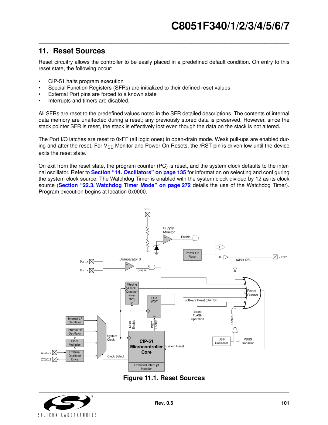
Reset circuitry allows the controller to be easily placed in a predefined default condition. On entry to this reset state, the following occur:
•
•Special Function Registers (SFRs) are initialized to their defined reset values
•External Port pins are forced to a known state
•Interrupts and timers are disabled.
All SFRs are reset to the predefined values noted in the SFR detailed descriptions. The contents of internal data memory are unaffected during a reset; any previously stored data is preserved. However, since the stack pointer SFR is reset, the stack is effectively lost even though the data on the stack is not altered.
The Port I/O latches are reset to 0xFF (all logic ones) in
On exit from the reset state, the program counter (PC) is reset, and the system clock defaults to the inter- nal oscillator. Refer to Section “14. Oscillators” on page 135 for information on selecting and configuring the system clock source. The Watchdog Timer is enabled with the system clock divided by 12 as its clock source (Section “22.3. Watchdog Timer Mode” on page 272 details the use of the Watchdog Timer). Program execution begins at location 0x0000.
VDD
Px.x ![]()
Px.x ![]()
![]()
|
|
|
| Internal LF |
| |
|
|
|
| Oscillator |
| |
|
|
|
|
|
|
|
|
|
|
| Internal HF |
| |
|
|
|
| Oscillator |
| |
|
|
|
|
|
|
|
|
|
|
|
|
|
|
|
|
|
| Clock |
| |
|
|
|
| Multiplier |
| |
|
|
|
|
|
|
|
|
|
|
|
|
|
|
|
|
|
| External |
| |
XTAL1 |
| |||||
Oscillator |
| |||||
XTAL2 |
|
|
| |||
| Drive |
| ||||
|
| |||||
Supply
Monitor
+Enable
-
|
|
|
|
|
|
|
| Power On |
|
|
|
|
|
Comparator 0 | Reset | '0' |
|
| /RST | |
| ||||||
|
|
|
| |||
|
|
|
| |||
+ |
|
|
|
- | C0RSEF |
|
|
|
|
| |
Missing |
|
|
|
Clock |
|
| Reset |
Detector |
|
| |
(one- | PCA |
| Funnel |
shot) | Software Reset (SWRSF) |
| |
EN | WDT |
| |
|
| ||
|
|
| |
|
| Errant |
|
| EN | FLASH | Enable |
MCD Enable | WDT Enable | Operation | |
| |||
System |
| USB | VBUS |
Clock |
| ||
| Controller | Transition | |
Microcontroller | System Reset |
| |
| Core |
|
|
Clock Select
Extended Interrupt
Handler
Figure 11.1. Reset Sources
Rev. 0.5 | 101 |