C8051F340/1/2/3/4/5/6/7

11.1. Power-On Reset

During power-up, the device is held in a reset state and the /RST pin is driven low until VDD settles above

VRST. A Power-On Reset delay (TPORDelay) occurs before the device is released from reset; this delay is typically less than 0.3 ms. Figure 11.2. plots the power-on and VDD monitor reset timing.

On exit from a power-on reset, the PORSF flag (RSTSRC.1) is set by hardware to logic 1. When PORSF is set, all of the other reset flags in the RSTSRC Register are indeterminate (PORSF is cleared by all other resets). Since all resets cause program execution to begin at the same location (0x0000) software can read the PORSF flag to determine if a power-up was the cause of reset. The content of internal data mem- ory should be assumed to be undefined after a power-on reset. The VDD monitor is enabled following a power-on reset.

Software can force a power-on reset by writing ‘1’ to the PINRSF bit in register RSTSRC.

volts

VDD

2.70

VRST

2.4


2.0


1.0


t

Logic HIGH

/RST

Logic LOW

TPORDelay


VDD

Power-On

Monitor

Reset

Reset

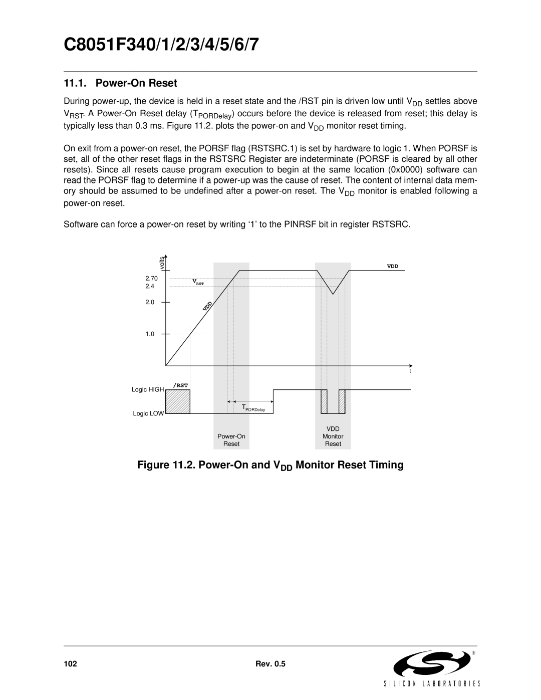
Figure 11.2. Power-On and VDD Monitor Reset Timing

102

Rev. 0.5

Page 102
Image 102
Silicon Laboratories C8051F345, C8051F347, C8051F346, C8051F341 Power-On Reset, Power-On and VDD Monitor Reset Timing