C8051F340/1/2/3/4/5/6/7
22.3. Watchdog Timer Mode
A programmable watchdog timer (WDT) function is available through the PCA Module 4. The WDT is used to generate a reset if the time between writes to the WDT update register (PCA0CPH4) exceed a specified limit. The WDT can be configured and enabled/disabled as needed by software.
With the WDTE and/or WDLCK bits set to ‘1’ in the PCA0MD register, Module 4 operates as a watchdog timer (WDT). The Module 4 high byte is compared to the PCA counter high byte; the Module 4 low byte holds the offset to be used when WDT updates are performed. The Watchdog Timer is enabled on reset. Writes to some PCA registers are restricted while the Watchdog Timer is enabled.
22.3.1. Watchdog Timer Operation
While the WDT is enabled:
•PCA counter is forced on.
•Writes to PCA0L and PCA0H are not allowed.
•PCA clock source bits
•PCA Idle control bit (CIDL) is frozen.
•Module 4 is forced into Watchdog Timer mode.
•Writes to the Module 4 mode register (PCA0CPM4) are disabled.
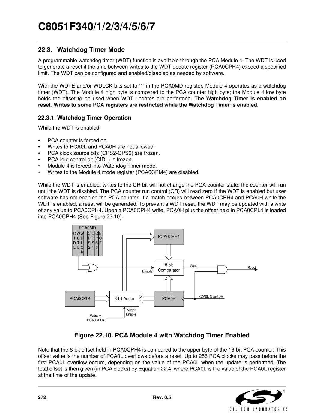
While the WDT is enabled, writes to the CR bit will not change the PCA counter state; the counter will run until the WDT is disabled. The PCA counter run control (CR) will read zero if the WDT is enabled but user software has not enabled the PCA counter. If a match occurs between PCA0CPH4 and PCA0H while the WDT is enabled, a reset will be generated. To prevent a WDT reset, the WDT may be updated with a write of any value to PCA0CPH4. Upon a PCA0CPH4 write, PCA0H plus the offset held in PCA0CPL4 is loaded into PCA0CPH4 (See Figure 22.10).
PCA0MD
C | W | W |
| C | C | C | E |
| ||
I | D | D |
| P | P | P | C |
| ||
D | T | L |
| S | S | S | F |
| ||
L | E | C |
| 2 | 1 | 0 |
|
| ||
|
| K |
|
|
|
|
|
|
| |
|
|
|
|
|
|
|
|
|
|
|
|
|
|
|
|
|
|
|
|
|
|
|
|
|
|
|
|
|
|
|
|
|
Enable
PCA0CPH4
Comparator
Match | Reset |
|
PCA0CPL4 |
|
| PCA0H | |
|
|
|
|
|
PCA0L Overflow
Write to
Adder
Enable
PCA0CPH4
Figure 22.10. PCA Module 4 with Watchdog Timer Enabled
Note that the
272 | Rev. 0.5 |