C8051F340/1/2/3/4/5/6/7
SFR Definition 13.2. EMI0CF: External Memory Configuration
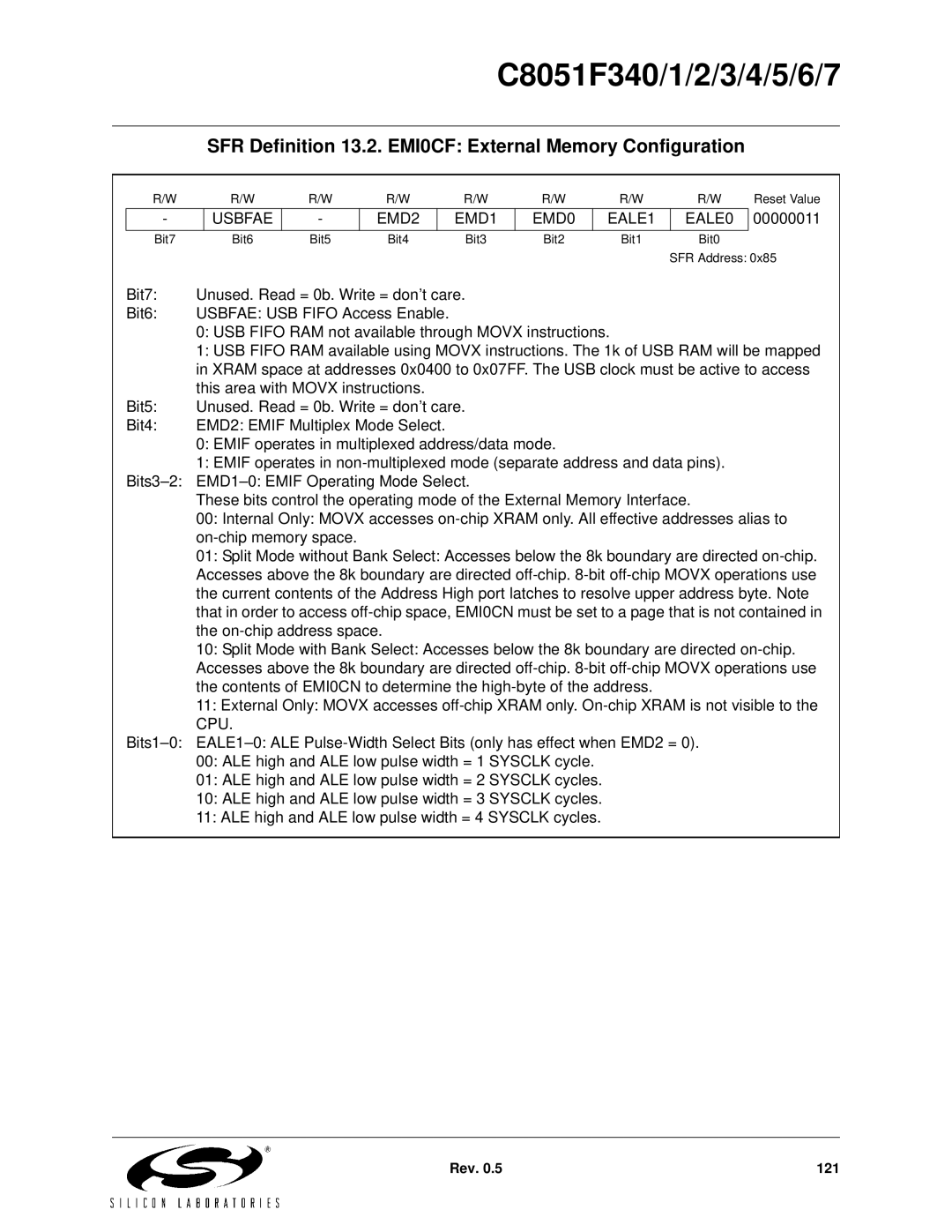
R/W | R/W | R/W | R/W | R/W | R/W | R/W | R/W | Reset Value |
-
USBFAE
-
EMD2
EMD1
EMD0
EALE1
EALE0
00000011
Bit7 | Bit6 | Bit5 | Bit4 | Bit3 | Bit2 | Bit1 | Bit0 |
SFR Address: 0x85
Bit7: | Unused. Read = 0b. Write = don’t care. |
Bit6: | USBFAE: USB FIFO Access Enable. |
| 0: USB FIFO RAM not available through MOVX instructions. |
| 1: USB FIFO RAM available using MOVX instructions. The 1k of USB RAM will be mapped |
| in XRAM space at addresses 0x0400 to 0x07FF. The USB clock must be active to access |
| this area with MOVX instructions. |
Bit5: | Unused. Read = 0b. Write = don’t care. |
Bit4: | EMD2: EMIF Multiplex Mode Select. |
0:EMIF operates in multiplexed address/data mode.
1:EMIF operates in
These bits control the operating mode of the External Memory Interface.
00:Internal Only: MOVX accesses
01:Split Mode without Bank Select: Accesses below the 8k boundary are directed
10:Split Mode with Bank Select: Accesses below the 8k boundary are directed
11:External Only: MOVX accesses
00:ALE high and ALE low pulse width = 1 SYSCLK cycle.
01:ALE high and ALE low pulse width = 2 SYSCLK cycles.
10:ALE high and ALE low pulse width = 3 SYSCLK cycles.
11:ALE high and ALE low pulse width = 4 SYSCLK cycles.
Rev. 0.5 | 121 |