C8051F340/1/2/3/4/5/6/7
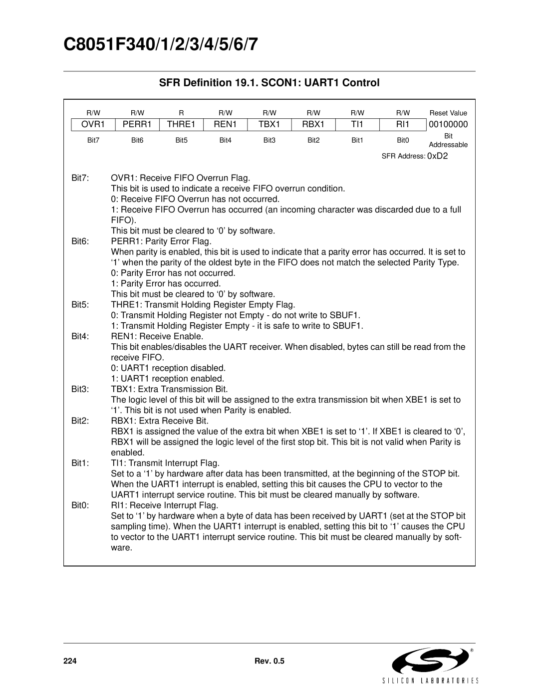
SFR Definition 19.1. SCON1: UART1 Control
R/W | R/W | R | R/W | R/W | R/W | R/W | R/W | Reset Value |
OVR1
PERR1
THRE1
REN1
TBX1
RBX1
TI1
RI1
00100000
Bit7 | Bit6 | Bit5 | Bit4 | Bit3 | Bit2 | Bit1 | Bit0 | Bit | |
Addressable | |||||||||
|
|
|
|
|
|
|
| ||
|
|
|
|
|
|
| SFR Address: 0xD2 | ||
Bit7: | OVR1: Receive FIFO Overrun Flag. |
|
|
|
|
| |||
| This bit is used to indicate a receive FIFO overrun condition. |
|
|
| |||||
| 0: Receive FIFO Overrun has not occurred. |
|
|
|
| ||||
| 1: Receive FIFO Overrun has occurred (an incoming character was discarded due to a full | ||||||||
| FIFO). |
|
|
|
|
|
|
| |
| This bit must be cleared to ‘0’ by software. |
|
|
|
| ||||
Bit6: | PERR1: Parity Error Flag. |
|
|
|
|
|
| ||
| When parity is enabled, this bit is used to indicate that a parity error has occurred. It is set to | ||||||||
| ‘1’ when the parity of the oldest byte in the FIFO does not match the selected Parity Type. | ||||||||
| 0: Parity Error has not occurred. |
|
|
|
|
| |||
| 1: Parity Error has occurred. |
|
|
|
|
| |||
| This bit must be cleared to ‘0’ by software. |
|
|
|
| ||||
Bit5: | THRE1: Transmit Holding Register Empty Flag. |
|
|
|
| ||||
| 0: Transmit Holding Register not Empty - do not write to SBUF1. |
|
| ||||||
| 1: Transmit Holding Register Empty - it is safe to write to SBUF1. |
|
| ||||||
Bit4: | REN1: Receive Enable. |
|
|
|
|
|
| ||
| This bit enables/disables the UART receiver. When disabled, bytes can still be read from the | ||||||||
| receive FIFO. |
|
|
|
|
|
|
| |
| 0: UART1 reception disabled. |
|
|
|
|
| |||
| 1: UART1 reception enabled. |
|
|
|
|
| |||
Bit3: | TBX1: Extra Transmission Bit. |
|
|
|
|
| |||
| The logic level of this bit will be assigned to the extra transmission bit when XBE1 is set to | ||||||||
| ‘1’. This bit is not used when Parity is enabled. |
|
|
|
| ||||
Bit2: | RBX1: Extra Receive Bit. |
|
|
|
|
|
| ||
| RBX1 is assigned the value of the extra bit when XBE1 is set to ‘1’. If XBE1 is cleared to ‘0’, | ||||||||
| RBX1 will be assigned the logic level of the first stop bit. This bit is not valid when Parity is | ||||||||
| enabled. |
|
|
|
|
|
|
| |
Bit1: | TI1: Transmit Interrupt Flag. |
|
|
|
|
| |||
| Set to a ‘1’ by hardware after data has been transmitted, at the beginning of the STOP bit. | ||||||||
| When the UART1 interrupt is enabled, setting this bit causes the CPU to vector to the | ||||||||
| UART1 interrupt service routine. This bit must be cleared manually by software. |
| |||||||
Bit0: | RI1: Receive Interrupt Flag. |
|
|
|
|
|
| ||
| Set to ‘1’ by hardware when a byte of data has been received by UART1 (set at the STOP bit | ||||||||
| sampling time). When the UART1 interrupt is enabled, setting this bit to ‘1’ causes the CPU | ||||||||
| to vector to the UART1 interrupt service routine. This bit must be cleared manually by soft- | ||||||||
| ware. |
|
|
|
|
|
|
| |
224 | Rev. 0.5 |