C8051F340/1/2/3/4/5/6/7
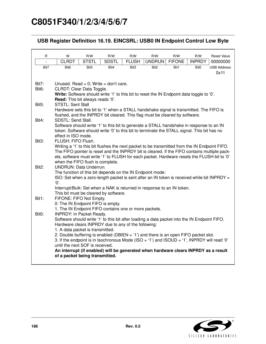
USB Register Definition 16.19. EINCSRL: USB0 IN Endpoint Control Low Byte
R | W | R/W | R/W | R/W | R/W | R/W | R/W | Reset Value |
- | CLRDT | STSTL | SDSTL | FLUSH | UNDRUN | FIFONE | INPRDY |
Bit7 | Bit6 | Bit5 | Bit4 | Bit3 | Bit2 | Bit1 | Bit0 |
00000000
USB Address:
| 0x11 |
Bit7: | Unused. Read = 0; Write = don’t care. |
Bit6: | CLRDT: Clear Data Toggle. |
| Write: Software should write ‘1’ to this bit to reset the IN Endpoint data toggle to ‘0’. |
| Read: This bit always reads ‘0’. |
Bit5: | STSTL: Sent Stall |
| Hardware sets this bit to ‘1’ when a STALL handshake signal is transmitted. The FIFO is |
| flushed, and the INPRDY bit cleared. This flag must be cleared by software. |
Bit4: | SDSTL: Send Stall. |
| Software should write ‘1’ to this bit to generate a STALL handshake in response to an IN |
| token. Software should write ‘0’ to this bit to terminate the STALL signal. This bit has no |
| effect in ISO mode. |
Bit3: | FLUSH: FIFO Flush. |
| Writing a ‘1’ to this bit flushes the next packet to be transmitted from the IN Endpoint FIFO. |
| The FIFO pointer is reset and the INPRDY bit is cleared. If the FIFO contains multiple pack- |
| ets, software must write ‘1’ to FLUSH for each packet. Hardware resets the FLUSH bit to ‘0’ |
| when the FIFO flush is complete. |
Bit2: | UNDRUN: Data Underrun. |
| The function of this bit depends on the IN Endpoint mode: |
| ISO: Set when a |
| ‘0’. |
| Interrupt/Bulk: Set when a NAK is returned in response to an IN token. |
| This bit must be cleared by software. |
Bit1: | FIFONE: FIFO Not Empty. |
| 0: The IN Endpoint FIFO is empty. |
| 1. The IN Endpoint FIFO contains one or more packets. |
Bit0: | INPRDY: In Packet Ready. |
| Software should write ‘1’ to this bit after loading a data packet into the IN Endpoint FIFO. |
| Hardware clears INPRDY due to any of the following: |
| 1. A data packet is transmitted. |
| 2. Double buffering is enabled (DBIEN = ‘1’) and there is an open FIFO packet slot. |
| 3. If the endpoint is in Isochronous Mode (ISO = ‘1’) and ISOUD = ‘1’, INPRDY will read ‘0’ |
| until the next SOF is received. |
| An interrupt (if enabled) will be generated when hardware clears INPRDY as a result |
| of a packet being transmitted. |
186 | Rev. 0.5 |