C8051F340/1/2/3/4/5/6/7
14.4. 4x Clock Multiplier
The 4x Clock Multiplier allows a 12 MHz oscillator to generate the 48 MHz clock required for Full Speed USB communication (see Section “16.4. USB Clock Configuration” on page 170). A divided version of the Multiplier output can also be used as the system clock. See Section 14.5 for details on system clock and USB clock source selection.
The 4x Clock Multiplier is configured via the CLKMUL register. The procedure for configuring and enabling the 4x Clock Multiplier is as follows:
1.Reset the Multiplier by writing 0x00 to register CLKMUL.
2.Select the Multiplier input source via the MULSEL bits.
3.Enable the Multiplier with the MULEN bit (CLKMUL = 0x80).
4.Delay for >5 µs.
5.Initialize the Multiplier with the MULINIT bit (CLKMUL = 0xC0).
6.Poll for MULRDY => ‘1’.
Important Note: When using an external oscillator as the input to the 4x Clock Multiplier, the exter- nal source must be enabled and stable before the Multiplier is initialized. See Section 14.5 for details on selecting an external oscillator source.
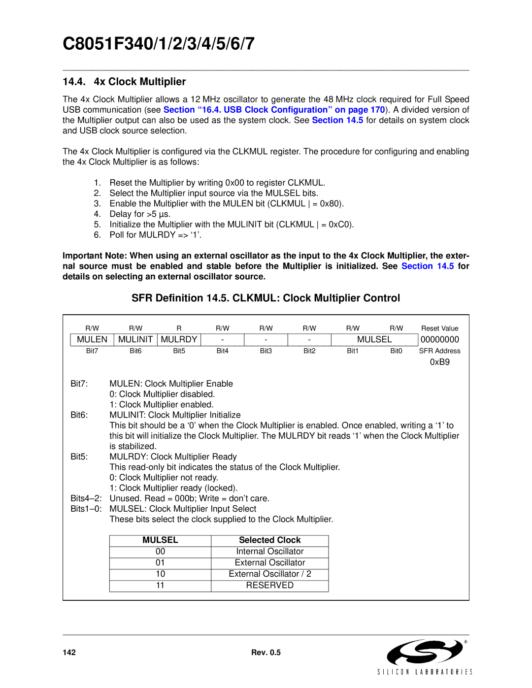
SFR Definition 14.5. CLKMUL: Clock Multiplier Control
| R/W |
| R/W |
| R | R/W |
| R/W | R/W | R/W | R/W | Reset Value | |||||
| MULEN |
| MULINIT |
| MULRDY |
|
| - |
| - |
| - |
|
| MULSEL | 00000000 | |
| Bit7 |
| Bit6 |
| Bit5 | Bit4 |
| Bit3 | Bit2 | Bit1 | Bit0 | SFR Address | |||||
|
|
|
|
|
|
|
|
|
|
|
|
|
|
|
|
| 0xB9 |
| Bit7: | MULEN: Clock Multiplier Enable |
|
|
|
|
|
|
|
|
| ||||||
|
| 0: Clock Multiplier disabled. |
|
|
|
|
|
|
|
|
|
| |||||
|
| 1: Clock Multiplier enabled. |
|
|
|
|
|
|
|
|
|
| |||||
| Bit6: | MULINIT: Clock Multiplier Initialize |
|
|
|
|
|
| |||||||||
|
| This bit should be a ‘0’ when the Clock Multiplier is enabled. Once enabled, writing a ‘1’ to | |||||||||||||||
|
| this bit will initialize the Clock Multiplier. The MULRDY bit reads ‘1’ when the Clock Multiplier | |||||||||||||||
|
| is stabilized. |
|
|
|
|
|
|
|
|
|
| |||||
| Bit5: | MULRDY: Clock Multiplier Ready |
|
|
|
|
|
| |||||||||
|
| This |
|
|
| ||||||||||||
|
| 0: Clock Multiplier not ready. |
|
|
|
|
|
|
|
|
| ||||||
|
| 1: Clock Multiplier ready (locked). |
|
|
|
|
|
| |||||||||
| Unused. Read = 000b; Write = don’t care. |
|
|
|
|
|
| ||||||||||
| MULSEL: Clock Multiplier Input Select |
|
|
|
|
|
| ||||||||||
|
| These bits select the clock supplied to the Clock Multiplier. |
|
|
| ||||||||||||
|
|
|
|
|
|
|
|
|
|
|
|
| |||||
|
|
| MULSEL |
|
| Selected Clock |
|
|
|
|
|
| |||||
|
|
|
| 00 |
|
|
| Internal Oscillator |
|
|
|
|
| ||||
|
|
|
| 01 |
|
|
| External Oscillator |
|
|
|
|
| ||||
|
|
|
| 10 |
|
| External Oscillator / 2 |
|
|
|
|
| |||||
|
|
|
| 11 |
|
|
|
| RESERVED |
|
|
|
|
|
| ||
|
|
|
|
|
|
|
|
|
|
|
|
|
|
|
|
|
|
142 | Rev. 0.5 |