C8051F340/1/2/3/4/5/6/7
22.4. Register Descriptions for PCA
Following are detailed descriptions of the special function registers related to the operation of the PCA.
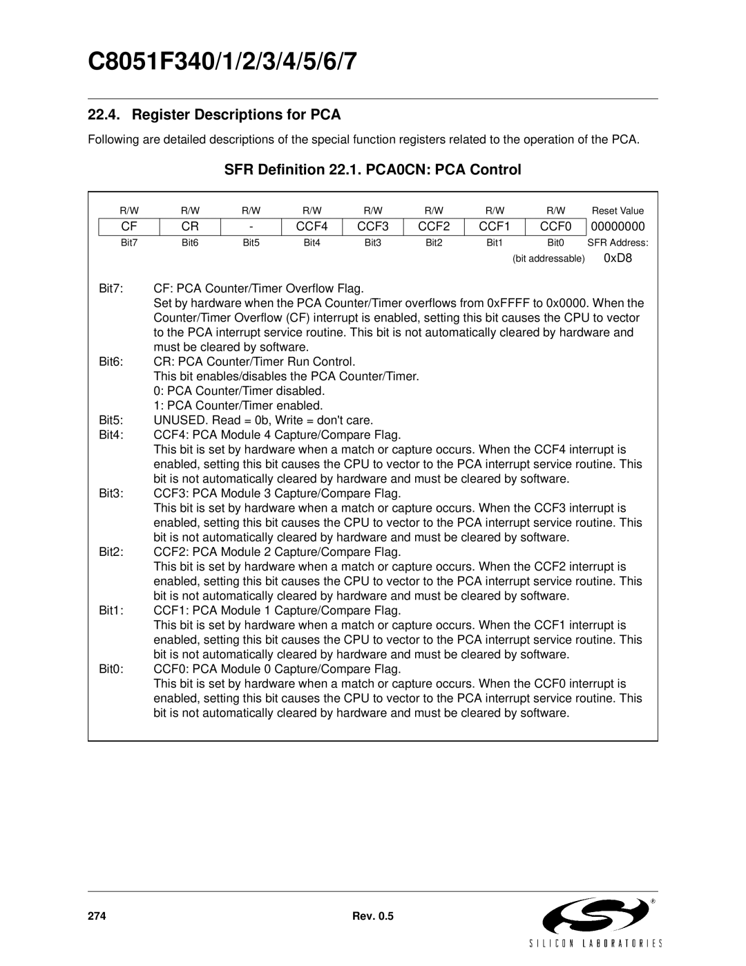
SFR Definition 22.1. PCA0CN: PCA Control
R/W | R/W | R/W | R/W | R/W | R/W | R/W | R/W | Reset Value |
CF
CR
-
CCF4
CCF3
CCF2
CCF1
CCF0
00000000
Bit7 | Bit6 | Bit5 | Bit4 | Bit3 | Bit2 | Bit1 | Bit0 | SFR Address: |
|
|
|
|
|
|
| (bit addressable) | 0xD8 |
Bit7: | CF: PCA Counter/Timer Overflow Flag. |
|
|
|
|
| ||
| Set by hardware when the PCA Counter/Timer overflows from 0xFFFF to 0x0000. When the | |||||||
| Counter/Timer Overflow (CF) interrupt is enabled, setting this bit causes the CPU to vector | |||||||
| to the PCA interrupt service routine. This bit is not automatically cleared by hardware and | |||||||
| must be cleared by software. |
|
|
|
|
| ||
Bit6: | CR: PCA Counter/Timer Run Control. |
|
|
|
|
| ||
| This bit enables/disables the PCA Counter/Timer. |
|
|
|
| |||
| 0: PCA Counter/Timer disabled. |
|
|
|
|
| ||
| 1: PCA Counter/Timer enabled. |
|
|
|
|
| ||
Bit5: | UNUSED. Read = 0b, Write = don't care. |
|
|
|
| |||
Bit4: | CCF4: PCA Module 4 Capture/Compare Flag. |
|
|
|
| |||
| This bit is set by hardware when a match or capture occurs. When the CCF4 interrupt is | |||||||
| enabled, setting this bit causes the CPU to vector to the PCA interrupt service routine. This | |||||||
| bit is not automatically cleared by hardware and must be cleared by software. |
| ||||||
Bit3: | CCF3: PCA Module 3 Capture/Compare Flag. |
|
|
|
| |||
| This bit is set by hardware when a match or capture occurs. When the CCF3 interrupt is | |||||||
| enabled, setting this bit causes the CPU to vector to the PCA interrupt service routine. This | |||||||
| bit is not automatically cleared by hardware and must be cleared by software. |
| ||||||
Bit2: | CCF2: PCA Module 2 Capture/Compare Flag. |
|
|
|
| |||
| This bit is set by hardware when a match or capture occurs. When the CCF2 interrupt is | |||||||
| enabled, setting this bit causes the CPU to vector to the PCA interrupt service routine. This | |||||||
| bit is not automatically cleared by hardware and must be cleared by software. |
| ||||||
Bit1: | CCF1: PCA Module 1 Capture/Compare Flag. |
|
|
|
| |||
| This bit is set by hardware when a match or capture occurs. When the CCF1 interrupt is | |||||||
| enabled, setting this bit causes the CPU to vector to the PCA interrupt service routine. This | |||||||
| bit is not automatically cleared by hardware and must be cleared by software. |
| ||||||
Bit0: | CCF0: PCA Module 0 Capture/Compare Flag. |
|
|
|
| |||
| This bit is set by hardware when a match or capture occurs. When the CCF0 interrupt is | |||||||
| enabled, setting this bit causes the CPU to vector to the PCA interrupt service routine. This | |||||||
| bit is not automatically cleared by hardware and must be cleared by software. |
| ||||||
274 | Rev. 0.5 |