C8051F340/1/2/3/4/5/6/7
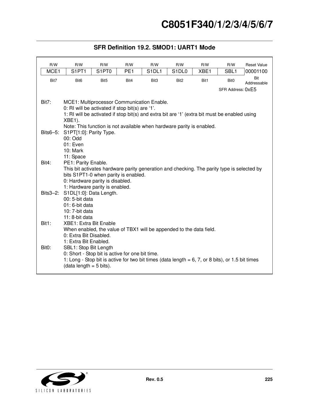
SFR Definition 19.2. SMOD1: UART1 Mode
R/W | R/W | R/W | R/W | R/W | R/W | R/W | R/W | Reset Value |
MCE1
S1PT1
S1PT0
PE1
S1DL1
S1DL0
XBE1
SBL1
00001100
Bit7 | Bit6 | Bit5 | Bit4 | Bit3 | Bit2 | Bit1 | Bit0 | Bit | |
Addressable | |||||||||
|
|
|
|
|
|
|
| ||
|
|
|
|
|
|
| SFR Address: 0xE5 | ||
Bit7: | MCE1: Multiprocessor Communication Enable. |
|
|
|
| ||||
| 0: RI will be activated if stop bit(s) are ‘1’. |
|
|
|
| ||||
| 1: RI will be activated if stop bit(s) and extra bit are ‘1’ (extra bit must be enabled using | ||||||||
| XBE1). |
|
|
|
|
|
|
| |
| Note: This function is not available when hardware parity is enabled. |
|
| ||||||
S1PT[1:0]: Parity Type. |
|
|
|
|
|
| |||
| 00: Odd |
|
|
|
|
|
|
| |
| 01: Even |
|
|
|
|
|
|
| |
| 10: Mark |
|
|
|
|
|
|
| |
| 11: Space |
|
|
|
|
|
|
| |
Bit4: | PE1: Parity Enable. |
|
|
|
|
|
| ||
| This bit activates hardware parity generation and checking. The parity type is selected by | ||||||||
| bits |
|
|
|
|
| |||
0:Hardware parity is disabled.
1:Hardware parity is enabled.
00:
01:
10:
11:
Bit1: | XBE1: Extra Bit Enable |
| When enabled, the value of TBX1 will be appended to the data field. |
| 0: Extra Bit Disabled. |
| 1: Extra Bit Enabled. |
Bit0: | SBL1: Stop Bit Length |
| 0: Short - Stop bit is active for one bit time. |
| 1: Long - Stop bit is active for two bit times (data length = 6, 7, or 8 bits), or 1.5 bit times |
| (data length = 5 bits). |
Rev. 0.5 | 225 |