C8051F340/1/2/3/4/5/6/7
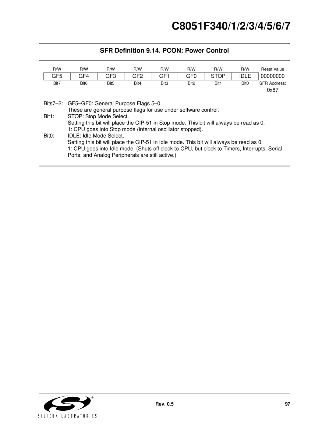
SFR Definition 9.14. PCON: Power Control
| R/W |
| R/W | R/W | R/W | R/W | R/W | R/W | R/W | Reset Value | |
| GF5 |
| GF4 | GF3 |
| GF2 | GF1 | GF0 | STOP | IDLE | 00000000 |
| Bit7 |
| Bit6 | Bit5 | Bit4 | Bit3 | Bit2 | Bit1 | Bit0 | SFR Address: | |
|
|
|
|
|
|
|
|
|
|
| 0x87 |
|
|
|
|
| |||||||
|
| These are general purpose flags for use under software control. |
|
| |||||||
| Bit1: | STOP: Stop Mode Select. |
|
|
|
|
|
| |||
|
| Setting this bit will place the | |||||||||
|
| 1: CPU goes into Stop mode (internal oscillator stopped). |
|
|
| ||||||
| Bit0: | IDLE: Idle Mode Select. |
|
|
|
|
|
| |||
|
| Setting this bit will place the | |||||||||
|
| 1: CPU goes into Idle mode. (Shuts off clock to CPU, but clock to Timers, Interrupts, Serial | |||||||||
|
| Ports, and Analog Peripherals are still active.) |
|
|
|
| |||||
|
|
|
|
|
|
|
|
|
|
|
|
Rev. 0.5 | 97 |