CoreBuilder ATM Enterprise Switch Management Guide
3Com Corporation 5400 Bayfront Plaza Santa Clara, California
Contents
Management Capabilities Starting Up LMA Access Level Logging
Logging Out
Set Management Configuration to Factory Defaults
Reset All
Reset Switch
116 Update Auto-discovery status 117
122 Update Ilmi Channel Polling Interval 123
103 Display Software Versions 104
105
134
Get ATM Addresses at Port 135
136 Network Prefix Display Network Prefix
148
189
190
192 ATM-Layer Statistics 193
198 AAL5-Layer Statistics 199
Update Startup Delay 223 Lane Version of Switch 224
218
222
229
289 Update Elan Response Policy 291
Reset LES Configurations 298
252 Display Elan MAC Addresses 254
255 Add Elan MAC Address 256 Display Elan ATM Addresses 257
Update LEC Elan Join Privilege for Current Session
Configuring Pnni Nodes 333 Get Number of Nodes 334
306 Display LAN Emulation Statistics
308
344 Set Default ATM Address 345
343
346 Get Peer Group ID
358
389
394
407 Display Ptse Node Information 412
414 Display Summary Address Table 416
ATM Switch Fabric Module Specifications Physical
Menu Index Technical Support
About this Guide
Conventions
List conventions that are used throughout this guide
Text Conventions
Icon Description
Conventions
Command Actions
Command Result
Parameter Format or Range
Explains the command descriptions
Command Description Sections
Key Section Description
CoreBuilder 9000 Documentation Overview
Paper Documents
Module Quick Start Guides or Getting Started Guides
Documents on CD-ROM
An ATM network
Year
Compliance
About this Guide
CoreBuilder ATM Enterprise Switch Characteristics
CoreBuilder 9000 ATM Enterprise Switch has two components
ATM Switch Fabric Module The ATM Interface Module
ATM Interfaces
Module Type No. of Ports Rate Mbps
Card Type 3Com Part Number
Mechanisms for Preventing Congestion
Preventing congestion Handling congestion
Mechanisms for Handling Congestion
Classical IP Clip ATM
Virtual Networks
Call Admission CLP-based Cell Discard
Key Features
Software Release
Standards
Protocols
Supported
Overview
Starting UP
Handling
Précautions de
Sécurité
Switch Fabric ATM
Manipulation
Poignées d’insertion/d’éjection sont ouvertes
Vorkehrungen beim Umgang mit dem Modul
Installation
CoreBuilder 9000 Enterprise Switch
Switch Integrated
Fast Setup
CoreBuilder
Integrated Fast Setup Procedure Sections
Integrated Fast Setup Procedure Navigation Aids
Setup Section Description
Sections
Management
Capabilities
Starting Up
Access Levels
Access Level Privileges
LMA Main Menu
LMA Menu System
LMA Menu Structure
At the Platform Configuration Menu prompt, enter
At the Switch Setup Menu prompt, enter
Entering the Menu Sequence
Entering the Command Parameters
Password in a format of up to eight alphanumeric characters
Password again exactly as before
Command Results
Menu Navigation Functions
Editing Aids
To go Type or Press
To perform this task Type or Press
Automatic Logout
Configuring the Platform
Update Admin-access Password Set Password to Factory Default
Read-access password is updated
Example
Write-access password is updated
Before you enter the new password
Admin-access password is updated
Passwords are reset to their factory values
Enter 1 1 1 Following prompt is displayed
Enter y to confirm. The following message appears
Setting Up for
Following message is displayed
Current IP address is displayed
MNG Management setup
SIP IP Setup
Next reboot
SIP Set IP Address
Current NMS IP address is displayed
NMS address is updated to
NMS NMS Setup
Example Enter 1 1
SNS Set NMS Address
Current default gateway IP address is displayed
Address found in the local IP subnetwork
GWY Default Gateway Setup
SGW Set Default Gateway
Default Gateway address was
Successfully set for the next reboot
Current IP subnet mask configuration is displayed
Address
MSK Subnet Mask Setup
Set for the next reboot
SSM Set Subnet Mask
Subnet Mask address was successfully
Enterprise Switch
Community String
Current read community string is displayed
Update Read
Update the Read Community String of the CoreBuilder 9000 ATM
ATM Enterprise Switch
Current write community string is displayed
Update Write
Current Ethernet Type configuration is displayed
ETH Ethernet Type Setup
SET Set Ethernet Type
Eth Type was successfully set for
Reboot
Management Configuration is set to the factory defaults
Enter 1 1 2 Following prompt is displayed
Setting the Port Network Connection Type
Command Actions
UNI
Port 1 7.1.2 7.1.3 7.1.4 7.2.1 7.2.2 7.2.3
Network connection type for port 3.1.2 is updated to UNI
Enter y to confirm. The following message is displayed
NNI configuration parameters are reset to UNI for all ports
UNI for all ports, and 7 for maximum number of hops
Enter 1 1 3 Following prompt is displayed
Resetting All
CoreBuilder 9000 ATM Enterprise Switch
Parameters
Enter 1 2 Following messages are displayed
Parameters
Enter 1 Following message is displayed
Download Status Command Actions
Downloading
System Software
Display Software
Download Messages
Message Meaning and Action
Download procedure
Enter 1 3 Following prompts are displayed
Load Mode Description
Load Modes
Configuration is uploaded to the host
Host
Enter 1 3 Following message is displayed
Managing Switch
Fabric Modules
Module Status
Switch Fabric Module Parameters
Switch Fabric Module Parameters
Name Description
Switch is rebooted and the following messages are displayed
Enter 1 4 Following prompt is displayed
Reset Standby Switch Reset the standby switch fabric module
Fabric Module Command Actions
Enter 1 4 3 Following prompt is displayed
Mode Command Actions
Direct access sequence 1 4 3 3
Configuring
Interface Modules
Display Interface
Module Information
Interface Module Slot Occupancy Parameters
Example for the 16-slot chassis and 7-slot chassis
Slot ID Parameters
Parameter Description
Interface Card Parameters
Interface Parameters
OC3-SC
Enter 1 5 3 5.1.1 Following messages are displayed
Selected ports are set and saved
Clock operational mode of port 1.1.2 is set to loop timing
Enter 1 5 4 1.1.2 Following message is displayed
Loop mode of port 1.1.2 is set to Loop back
Enter 1 5 5 1.1.2 Following messages are displayed
RST Reset Interface Card
Interface card was reset
Enter 1 5 6 Following prompt is displayed
IFC Interface Cards
Logging Out and Rebooting
Enter System is logged out
Reboot Reboot the system Command Actions
Parameter Format or Range Confirm reboot
Reboots the ATM Enterprise Switch
Enter 1 Following prompt is displayed
Direct access sequence 1
ATM Features
Display ATM Features
Software Versions
Latest software version numbers
Display Lecs ATM Address Update Lecs ATM Address
SLE LE Setup
LCS Lecs Setup
SLA Set Active Lecs ATM Addr
Active Lecs addraddress
Setting Up
Switch Clock Source
Get Clock Source
Status
Source
Cannot be used as an external clock source port
SP2 Set External Clock Source
Internal Command Actions
Enter 1 8 Following prompt is displayed
Ilmi Setup
IME Ilmi Setup
VER Ilmi Version Setup
GET Get Ilmi Version
Ilmi version is 3.0/3.1/4.0
Ilmi version of port 3.1.2 is updated to
Ilmi version is reconfigured
Example Enter
SET Set & Save Ilmi Version
Enter 1 1 8 2 1
Auto-configuration status of port 3.1.2 is enabled
AUD Auto-Discovery Setup
SET Set & Save Auto-Discovery
MIB Ilmi MIB View Setup
Lecs via Ilmi is ENABLED/DISABLED
GET Get Lecs via Ilmi
ON/OFF Status
LECS-via-ILMI status of port 3.1.2 is enabled
Enter 1 1 8 4 1
8 4
VPI/VCI = 0/16 is periodically polled for connectivity
Enter 1 1 8 4 4 3.1.2
ATM Addresses Port
Display User
Addresses at Port
Enter the menu sequence 3 CON Connections
Enter 3 1 1
Describes the UME parameters displayed by the command
UME Parameters
UME Parameters
CON Connections
ADD Get ATM Addresses
STC Get Static and NNI Addresses
At Port
Describes the parameters displayed by the command
Parameters
Port Command Actions
Parameters
Enter 3 4 2 1
C Setup of Connections and ATM
STP Static ATM Addresses Setup
Addresses
ADD Add ATM Address
DEL Delete ATM Address
ATM address member n was deleted from
Port
Enter 3 4 2 4
Enter 3 4 2 Following prompt is displayed
Network Prefix
Display Network
Prefix
Managing Network Interfaces
Configuring Virtual Channels
Signaling Setup Signaling Timers
Configuring Virtual Channels
RTG Routing CLL Calls
Example Display all SVC Calls for an ATM address member
Example Display Info for a Specific SVC Call
Example Display all PVC Calls for a Port
Two additional destinations
With two additional destinations
Shows the call parameters displayed by the command
Call Parameters
Call Parameters
Display Port Connections
Example Display all Connections at a Port
Example Display Info for a Connection at a Port
Port SVC Connection Parameters
Port SVC Connection Parameters
PRT ATM ports
Port Static Connection Parameters
Port Static Connection Parameters
Connections Command Actions
Create Permanent Virtual Channel PVC
Enter 3 4 1 Following information is displayed
Create Permanent Virtual Channel PVC
Direct access sequence 3 4 1 2 parameters
Full PVC Call Parameters
Enter 3 4 1 3 p2p 5.1.1 0 37 5.1.2 0
You cannot add an additional PVC destination to a P2P PVC
You cannot release SVCs with this menu
Parameter
Example Enter 3 4
PVC PVCs Setup
GEP Display PVCs
Enter y to confirm, n to cancel Following message appears
Following prompt appears
All inactive PVCs are deleted from the flash memory
Connections of Port Command Actions
All PVCs of the specific port are deleted
NNI Hops Setup
Display Maximum
NNI Hops
Maximum NNI Hops parameter is updated to
Signaling Setup
SIG Signaling Setup
VCC VPI/VCI range setup
GET Get VPI/VCI range
Following information is displayed for an OC-3c port
Following information is displayed for an OC-12c port
Information, see Display VPI/VCI Range on
Maximum VPI for port 3.1.2 is updated to
Protocol Profile
Enter 1 1 4 5
Enter 1 1 4 5 2 3.1.2
Following information is displayed
Protocol Version Parameters
Protocol Version Parameters
Enter 1 1 4 5 4 3.1.2
Display Call-Proceeding Enable Value
Display the value of the call-proceeding enable value
Enable Value Command Actions
Enter 1 1 Following message appears
Enter Y to confirm, N to cancel
Enter 1 1 4 Following prompt appears
Protocol timers
Half. For more information, see Timer Resolution on page 98
Response is overdue
Enter 1 1 4 1
Timer resolution is updated to 250 msec and saved to flash
RES Timer Resolution setup
SET Set Timer Resolution
Timer resolution was successfully set
Parameter Format or Range Port number Slot.group.port
4 2 parameters
Displayed in seconds
Enter 1 1 4 2
Sscop Timers
Shows the Sscop Timers displayed by the command
Sscop Timers
QSA Get Signaling Qsaal
Sscop Configuration Parameters
Sscop Configuration Parameters
Enter 1 1 4 4
Configuring Virtual Channels
Physical Layer
Statistics
Enter 4 1 1
Physical Layer Statistics
Statistic
Statistics Command Actions
Physical statistics are reset for port
Reset Counters Per Port Reset Counters Per VPI/VCI
ATM-Layer Statistics
Enter 4 2 Following information is displayed
Example Enter 4 2 Following information is displayed
Enter 4 2 3 1.1.1 3
ATM Counters for the specified port are reset to
RPR Reset counters per port
Reset ATM counters completed
ATM ATM layer
Counters are reset
Perform menu item 3CON\2RTG\1CLL to
Display AAL-Layer Statistics Reset AAL-Layer Statistics
AAL5-Layer Statistics
You can display the following AAL5-layer statistics
Enter 4 3 Following information is displayed
SAR Counters
Enter 4 3 Following message is displayed
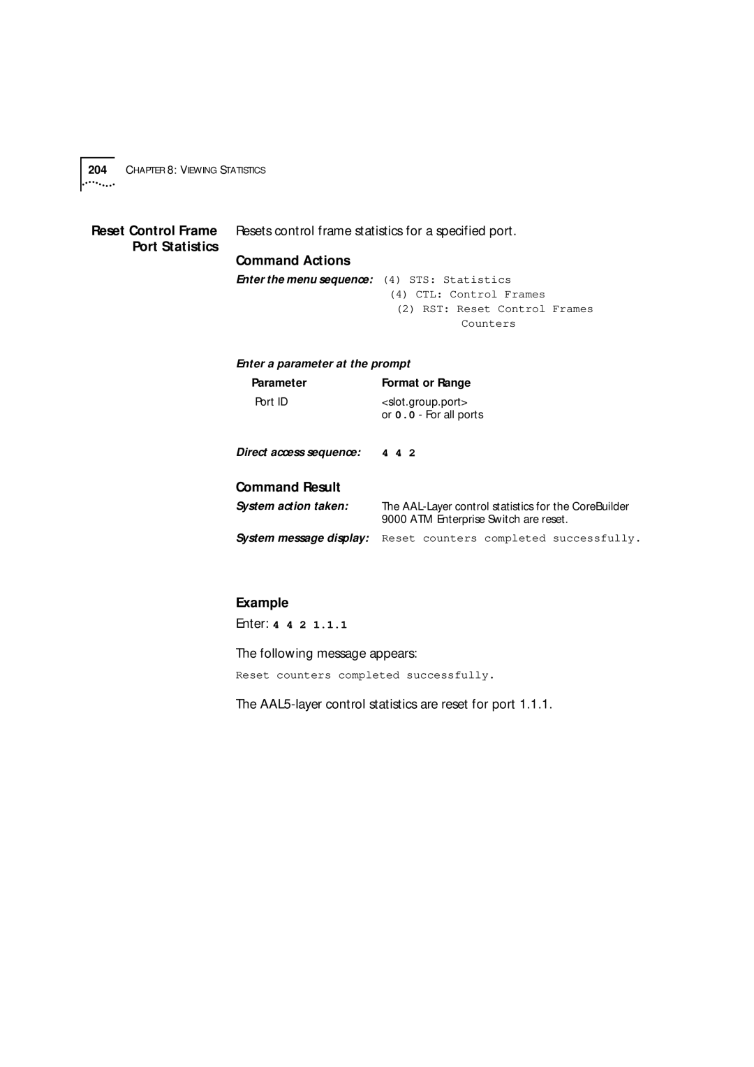
AAL5 Control Frame Port Statistics
You can display the following AAL5 control statistics
Enter 4 4 1
Port Statistics Command Actions
AAL5-layer control statistics are reset for port
Signaling Protocol Statistics
You can display the following signaling statistics
Enter 4 5 1
Counters Command Actions
Signaling statistics are reset for port
Viewing Statistics
Learp Policy Configuration LEC Operations
Managing LAN Emulation
Services Setup
LAN Emulation
Status Command Actions
5 1
LE service status will be Disabled on the next reboot
Direct access sequence 1 1 5 2
Lecs service status is set for the next reboot
Lecs is disabled
LAN Emulation Redundancy Setup
Enter 1 1 5 3
SYS Platform config
Lecs is entered into the LECS-order database
LOL Lecs ordered list
AOL Add to Lecs ordered list
Lecs with index 2 is removed from the LECS-order database
DOL Del from Lecs ordered list
Redundant Lecs deleted
LES Redundancy Parameters
LES Redundancy Parameters
Redundant Lane Services on page 137 in the Operations Guide
RDN LE Service redundancy setup
LRM Change LE Service
Redundancy Mode
LRD Set LE Service redundancy
Startup delay
Startup Delay Changed
600
Get Switch Lane
Version Command Actions
Lane Version
Not to a specific Elan
Lane version of the switch is changed
That join after the change
Parameter Format or Range Lane version
Configuration
Configuration Command Actions
Mpoa Devices
Display Current MPS
Mpoa Server Configuration Parameters
Describes the Mpoa Server configuration parameters
Mpoa Server Configuration Parameters
Variable Name Description
Enter 2 5 1 2
Lifetime Command Actions
Set Keep-AliveSets the MPS-p2 keep-alive lifetime parameter
Layer Protocols Command Actions
Set Internetwork Sets the MPS-p3 protocols parameter
Parameter Format or Range Internetwork-layer
Protocols
MPA Mpoa Devices Configuration
MPS Mpoa Server Configuration
LEM LAN Emulation
MP4 Set initial retry time
Maximum Command Actions
Set Retry Time Sets the MPS-p5 retry time maximum parameter
MP5 Set retry time maximum
10 300 seconds
Set Give Up Time Sets the MPS-p6 give-up time parameter
Time Command Actions
MP7 Set default holding time
Enter 2 5 2 Following information is displayed
Mpoa Client Configuration Parameters
Describes the Mpoa Client configuration parameters
Mpoa Client Configuration Parameters
Frame Count Command Actions
MPC Mpoa Client Configuration
Frame Time Command Actions
Protocols Command Actions
Parameter Format or Range Flow detection protocols
Flow detection protocols parameter is set
Command Result
Set Retry Time Sets the MPC-p5 retry time maximum parameter
Set Hold Down Time Sets the MPS-p6 hold down time parameter
MP6 Set hold down time
30 1200 seconds
You can configure the resident Lecs address as follows
Update Resident Lecs Address
Lecs Address
Display Resident Lecs Address
Address Command Actions
Bytes. The update takes place immediately
Resident Lecs address is updated
LCS LE Config Service
LSP Set resident Lecs addr
Command Actions
Enter 2 1 Search policy of the resident Lecs is displayed
Lecs Elan
Database Operations
Elan LES Parameters
Describes the Elan LES parameters
Elan LES Parameters
Database Command Actions
LCS LE Configuration Service
LNT Lecs network topology
LEP Display Elan type & params
Database that you can update
Elan Parameters in Lecs Database
Describes the Elan parameters in the Lecs database
Elan Parameters in Lecs Database
Enter 2 1 5 3 elan6914 1
Addresses Command Actions
MAC MAC Addresses Info
MAD Display all MAC addresses
Delete Elan MAC Delete a MAC address inserted from an Elan
Specified MAC address is deleted from the Elan
MAC MAC Address Info
DEL Delete MAC Address
Console responds with the confirmation
ATM ATM Address Info
AAD Display all ATM addresses
Specified ATM address is deleted from the Elan
ATM ATM Addresses Info
ATM address was deleted for this elan
System responds with the confirmation
ANE Add new Elan record
New elan was added
Enter 2 1 5
Confirmation message is displayed
DEL Delete Elan recor d
Elan record was deleted
Segment id has been updated
You cannot assign a segment ID to a non-token ring Elan
Segment ID is added to the Lecs database
SEG Edit segment id C23, for
Signaling Statistics Parameters
Describes the signaling statistics parameters
Lecs Statistics Parameters
Describes the Lecs statistics parameters
Enter 2 1 Lecs database statistics are displayed
Enter 2 1 Following prompt is displayed
Display Lecs Maximum Connection Number
Shows how many LECs the Lecs database may contain
Enter 2 1 8 Following message is displayed
Update Lecs Maximum Connection Number
Sets the number of LECs the Lecs database may contain
Number of Lecs
Connections
LAN Emulation Redundancy
RDN LE Service redundancy
ALS Add redundant LES to
Elan
Redundant LES successfully added
Enter 2 1 5 9 2 elan739
FEP Force Elan to Primary
Enter 2 1 5 9 3 elan739
Display Redundant ELANs General Information
Display general information about redundant ELANs
Redundant ELANs General Parameters
Describes the ELANs general parameters
Redundant ELANs General Parameters
Display Redundant ELANs Specific Information
Display specific information about Redundant ELANs
Redundant ELANs Specific Parameters
Describes the ELANs specific parameters
Redundant ELANs Specific Parameters
LES General Command Actions Information
Display general information on a redundant LES
Redundant LES General Parameters
Describes the redundant LES general parameters
LES Specific Information Command Actions
Enter 2 1 Following information is displayed
LES
You can configure the LES address, as follows
Update Elan LES-BUS Address
Display LES-BUS Addresses
Display LES-BUS
Enter 2 2 Following information is displayed
Enter 2 2 3 1 1 2 c0.da.60 .49
Direct access sequence 2 2
Enter 2 2 Following information is displayed
Elan Parameters for Resident LESs
Describes the Elan parameters for resident LESs
Elan #4 is of Token Ring type
Elan Parameters for Resident LESs
Database
Parameters of the Elan with ID 14 are updated
Describes the Elan parameters that can be updated
Elan Parameters for a LES
Elan Parameters for a LES
Learp Policy Configuration
Display Elan Response Policy
Elan Response Policies
Describes the Elan response policies
Elan Response Policies
Enter 2 2 Following messages are displayed
Possible Learp policies
Learp Verification Policies
Describes the Learp verification policies
Learp policies
Learp Verification Policies
Enter 2 2 3 1 5 2
Managing LAN Emulation
Example Enter 2 2
Learp Policies for Route Descriptor
Describes the Learp policies for the route descriptor
Learp Policies for Route Descriptor
Enter 2 2 3 1 7 2
Response policy, and Learp response policies
Following prompt appear
Direct access sequence 2 2 3 1
Update Lane Multicast Forward Delay
Update the Lane multicast forward delay parameter
Lane multicast forward delay time is updated
Enter 2 2 Following message appears
LEC Operations
Display LEC
Connection Info
LEC Connection Information Parameters
LEC Connection Information
ADD Clients MAC Addresses
Lecid
Emulation Statistics Command Actions
Display LAN
Enter 2 2 3 4 1
Enter 2 2 3 4 2 2
LEC Statistics
Describes the LEC statistics parameters
LEC Statistics
NameDescription
LES LE Services
RES Reset General LE
ELN ELANs Information
Statistics
Enter 2 2 3 Following message is displayed
DSL Destroy specific LEC
Enter Y to confirm, N to cancel the reset request
Enter 2 2 5 Following prompt appears
Managing LAN Emulation
LEC Elan Admission Security
Enter 2 3 1 1
Enter 2 3 1 2 1
LECs in Elan
Security List
Security List
Enter 2 3 2 1
Session
Command to initialize the Elan security list
Enter 2 3 2 4 1 47.0.0.0.0.0.3c.0.0.a0
Enter Y to continue, N to cancel
Enter 2 3 2 6 1
CHK Perform a security check
Switch Security
Display Switch
Security Status Command Actions
SEC LE Security Configuration
SWS Switch security
SST Set switch security state
Security on switch now Enabled
Restore Security Configuration
Save Security
Save Security
Direct access sequence 2 3
LEC Elan Admission Security
Configuring the Route Cache Showing Pnni Information
Pnni
Following command allows you to view the current Pnni state
Viewing
Current Pnni State
Display PNNI/E-IISP State
Configuring Pnni
Nodes
Enter 1 1 9 4 1
State Operations Guide for more information on E.164
196 in the Operations Guide for more information on E.164
Enter 1 1 Following message is displayed
Enter 1 1 9 4 3 1
Enter 1 1 9 4 3 2
To UP Command Actions
Pnni node administrative status is set to UP
To Down reboot Command Actions
Pnni node administrative status is set to Down
PDB Purge whole Pnni
Enter 1 1 9 4 3 3 1
Following message is 7displayed
Node level of node 1 is set to
3 3 2
Default ATM address takes place after the next reboot
9 4 3 3 2 3 parameters
Address is updated to its new value
9 4 3 3 3
3 3 3
9 4 3 3 4
3 3 4
SID Set Node ID
Node ID is updated to its new value
3 3 5
Name of the node is updated to 3Com World
9 4 3 3 6
9 4 3 3 6 2 parameters
Configuring and Managing Pnni
9 4 3 4 1 parameters
9 4 3 4 2 parameters
9 4 3 4 3 parameters
9 4 3 4 4 parameters
9 4 3 4 5 parameters
9 4 3 4 6 parameters
Interval takes place after the next reboot
9 4 3 4 8 parameters
9 4 3 4 9 parameters
9 4 3 4 10 parameters
9 4 3 4 11 parameters
9 4 3 4 12 parameters
9 4 3 4 13 parameters
Enter 1 1 9 4 3 4 14
Enter 1 1 9 4 3 4 15
Enter 1 1 9 4 3 4 16
Default Values Command Actions
All the timers are set to the default values
Setting Optimization Metrics
Classes of Service
Optimization Metrics Table Parameters
Optimization Values
Value Description
Value of the CBR optimization parameter is updated
Value of the RealTime-VBR optimization parameter is updated
9 4 3 5 2 3 parameters
9 4 3 5 2 4 parameters
Value of the UBR optimization parameter is updated to
All Classes to Default Command Actions
Select Port for Interface Parameter Setting
Parameter Format or Range Port number Slot.subslot.port
Configuring and Managing Pnni
9 4 4 2 1 parameters
Weight bit rate service category
9 4 4 2 3 parameters
9 4 4 2 4 parameters
9 4 4 2 5 parameters
Weight unspecified bit rate service category
9 4 4 2
To Default Values Command Actions
Managing Scope Mapping
Scope Mapping Table Parameters
Scope Mapping Table Parameters
Pnni Scope
PnniScopeLocalNetworkPlusTwo
Enter 1 1 Following information is displayed
MST Modify Scope Mapping
Hierarchical level of pnniScopeGlobal is updated to
After the next reboot
Configuring the Route Cache
Get Cache State
SCS Set Cache State
Will continue to be used when an ADD Party route is added
11 1 9 10 4 6
After this number of calls, the cache will be refreshed
9 4 6 6 parameters
Following commands allow you to display Ptse and other Pnni
Showing Pnni
Information
Display All PTSEs
Ptse Table Parameters
Ptse Table Parameters Node Topology Link Section
Ptse Table Parameters Node Address Section
Ptse Table Parameters Statistics Section
Enter 1 1 9 4 7
Information Command Actions
Node Ptse Table Parameters
Example
Topology Link Ptse Table Parameters
Example
Address Table Command Actions
Summary Address Table Parameters
Node Address Ptse Table Parameters
Example
Peer Group Leader Table Parameters
Peer Group Leader Table Parameters
Enter 1 1 Following information is displayed
Neighbor Information Command Actions
Peer Group Neighbor Table Parameters
Information node is up Command Actions
Statistics Table Parameters
Safety
Physical
Environmental
Connectors
Electromagnetic Compatibility
Standards Supported
Interface LEDs
Management Setup
Menu Index
164
165
180
182
171
173
174
176
137
112
113
114
102
101
107
108
249
250
251
253
266
267
280
283
310
286
311
314
228
229
230
231
151
153
156
157
199
201
202
204
330
332
333
334
352
353
354
355
375
377
378
379
398
399
400
401
Appendix B Menu Index
Services
Services
Online Technical
3Com
Access by Analog Modem
Username anonymous
Hours a day, 7 days a week
Country Data Rate Telephone Number
Access by Digital Modem
847 262
408 727
Europe, South Africa, and Middle East
Country Telephone Number Asia, Pacific Rim
Country Telephone Number Fax Number
Appendix C Technical Support
Glossary
Module
Software LED
Application LMA
Indicator LED
Software Error LED
Module Status LED
Multiplexing
Glossary
Index
Numbers
Call admission control 28 call-proceeding enable value
Efci site marking 28 Elan emulated LAN
Learp
MIB II
Pnni
Ptse
Storage humidity 421 subnet mask configuration
Displaying 66 write-access password updating
Index
3Com Corporation Limited Warranty
Additional Services