Agilent 35670A Service Guide
Agilent 35670A at a Glance Front Panel
Agilent 35670A Front Panel
Agilent 35670A at a Glance Rear Panel
Plot/Print menus
Agilent 35670A Rear Panel
Saftey Summary
Do not Operate in AN Explosive Atmosphere
Safety Symbols
Available Accessories
Supplied Accessories
This Book
Table of Contents
Preparing the Analyzer for Use
Page
Troubleshooting the Analyzer
Adjusting the Analyzer
Replaceable Parts
Circuit Descriptions
Voltages and Signals
Specifications
Abbreviations
Specifications
Frequency
Channel mode option AY6 only
Average, 0 to −80 dBfs
Single Channel Amplitude
FFT Dynamic Range
Window Parameters
Single Channel Phase
Input Noise
Cross Channel Amplitude
Cross Channel Phase
Input
Trigger
Time Domain
Tachometer
Source Output
Gpib
Digital Interfaces
Cispr
General Specifications
Max Order⋅ Max RPM
Order Tracking Option 1D0
Arbitrary Waveform Source-Option 1D4
Swept Sine Measurements -Option 1D2
= 1, 3 or
Real Time Octave Analysis Option 1D1
Recommended Test Equipment
Suggested Assembly for Series Resistor
Schematic and Parts List for Notch Filter
TTL
Preparing the Analyzer for Use
AC Power Requirements
DC Power Requirements
Line voltage
Operating Typical Current Voltage Standard 2 channel
AC Power Cable and Grounding Requirements
DC Power Cable and Grounding Requirements
Preparing the Analyzer for Use
Subject the operator to lethal voltages
To do the incoming inspection
Set the analyzer’s power switch to on
Other excessive moisture
To install the analyzer
Connect the dc power cable to the dc power source
To connect the analyzer to a dc power source
Set the analyzer’s power switch to on l
Turn on the dc power source
Adapter, be careful of the heat from the adapter’s tip
At the end of this chapter
AC Fuse
To change the fuses
DC Fuse
Part Number Cable Description
To connect the analyzer to a serial device
To connect the analyzer to a parallel device
Reference
To connect the analyzer to an Gpib device
To connect the analyzer to an external monitor
Pin Number Signal Name
To connect the optional keyboard
Set the power switch to off O
Connect the other end of the keyboard cable to the keyboard
Standard 2 channel Agilent 35670A Optional 4 channel
To connect the microphone adapter
To store the analyzer
To clean the screen
To transport the analyzer
If the analyzer will not power up
Agilent 35670A
Verifying Specifications
Overview
Verifying Specifications
Test Duration
Features of the Program
Calibration Cycle
Recommended Test Equipment
Program Controlled Test Equipment
Operation Verification and Performance Tests
Measurement Uncertainty
Test Equipment Program Controlled Model
Operation Verification Tests Performance Tests
Specification Performance Test
Specifications and Performance Tests
Local/GPIB
Now go to one of the following procedures to continue
To load the program
To run the program in semiautomated mode
Voltages that could result in injury to personnel
Press the following keys to start the test
Follow the directions on the display
Press the following keys
To run the program without a printer
Agilent 35670A
To run the program in manual mode
To set up the self test
To set up the dc offset test
To set up the noise test
To set up the spurious signals test
To set up the amplitude accuracy test
To set up the flatness test
To set up the amplitude linearity test
To set up the A-weight filter test
To set up the channel match test
To set up the frequency accuracy test
To set up the anti-alias filter test
To set up the input coupling test
To set up the harmonic distortion test
2A 2 ch
Using a synthesizer and notch filter
To set up the intermodulation distortion test
2 ch
To set up the cross talk test
Verifying Specifications
Verifying Specifications
Agilent 35670A
To set up the single channel phase accuracy test
To set up the external trigger test
1A 2 ch
To set up the tach function test
To set up the tach function test
To set up the input resistance test
To set up the input resistance test
To set up the ICP supply test
To set up the ICP supply test
Agilent 35670A
Verifying Specifications
To set up the source amplitude accuracy test
To set up the source output resistance test
To set up the source output resistance test
To set up the source dc offset test
To set up the source flatness test
To set up the source distortion test
ITM35670A Main Menu Descriptions
Press Start Testing to display the following softkeys
Start Testing Menu Descriptions
Test Configuration Menu Descriptions
Equipment Configuration Menu Descriptions
Prompts you to enter the analyzer’s report number
Title Page Menu Descriptions
Measurement Uncertainty
±0.0020 dB 101 ±0.0026 dB ±0.0046 dB ±0.0096 dB ±0.0255 dB
Using Other Test Equipment
Test Instruments Used
Performance Test Record Two Channel
Noise
Self Test
DC Offset
Spurious Signals
Performance Test Record Two Channel
Agilent 35670A Verifying Specifications
Flatness
Amplitude Accuracy
−11 dBVrms, 99.84 kHz, One Ch, Ch
Amplitude Linearity
Channel Match
Weight Filter
Input Coupling
Frequency Accuracy
Anti-Alias Filter
Harmonic Distortion
Cross Talk
Intermodulation Distortion
Tach Function option D01 only
Single Ch Phase Accuracy
External Trigger
ICP Supply
Input Resistance
Source Amplitude Accuracy
Source Output Resistance
Source Distortion
Source DC Offset
Source Flatness
Performance Test Record Four Channel
Four Ch, 6.4 kHz Span, Ch
Four Ch, 0 Hz Start, Ch
Performance Test Record Four Channel
Agilent 35670A Verifying Specifications
Spurious Signals
Amplitude Accuracy
Serial NumberReport Number Test Date
−11 dBVrms, 25.6 kHz, Four Ch, Ch
Amplitude Linearity
Ch 3, 100 Hz
Two Ch, 2/1, − 13 dBV FS Mag
Performance Test Record Four Channel
One Ch, Ch 1, 51.2 kHz
Four Ch, 12.25 kHz 2nd, Ch
Two Ch, F1−2F2, 1048 Hz, Ch
Receiver Ch 1, Driver Ch 2, 3
Ch 31 Open Circuit Voltage
Ch 3 Current
12.8 kHz 25.6 kHz 51.2 kHz
Operation Verification Test Record Two Channel
Self Test
Operation Verification Test Record Two Channel
Operation Verification Test Record Two Channel
Spurious Signals
Operation Verification Test Record Two Channel
Ch 1, 10 Hz Ch 2, 10 Hz Ch 1, 31.62 Hz Ch 2, 31.62 Hz
Operation Verification Test Record Two Channel
Frequency Accuracy
Open Circuit Voltage
Operation Verification Test Record Four Channel
Verifying Specifications Agilent 35670A
Four Ch, 1400 Hz Start, Ch −80
Operation Verification Test Record Four Channel
Operation Verification Test Record Four Channel
Spurious Signals
Amplitude Accuracy
Serial NumberReport Number Test Date
Flatness
Amplitude Linearity
Weight Filter
Two Ch, 2/1, 7 dBV −20 dBfs Mag
Frequency Accuracy
Ch 3 Open Circuit Voltage
Source Amplitude Accuracy
Page
Troubleshooting the Analyzer
Safety Considerations
Troubleshooting the Analyzer
Equipment Required
Troubleshooting Hints
Symptom Troubleshooting Test
How to troubleshoot the analyzer
Failures.’’
To perform initial verification
Data appears
Symptom Probable Faulty Assembly
Power supply.’’
Connect the power cord and set the power switch to on l
Rear panel
Remove the cover
Signal Name Test Location Frequency Probable Faulty Assembly
A7 Component Locator, Circuit Side
Signal Name Test Location
Using a logic probe, check the following signals
Set the power switch to on l
To troubleshoot the power supply
Probably faulty
Reconnect the ribbon cable to the Power Supply assembly
A6 Digital A5 Analog A2 Input optional A1/A2 Input
Remove the A7 CPU assembly
Set the power switch to off O Remove the A7 CPU assembly
Entry closest to the beginning of the table
To troubleshoot power-up failures
Determine if the power-on test passed or failed
Binary Hexa ~Time LEDs Description DS5 DS9 Decimal Visible
Power-on LEDs Next Test
SW2
To troubleshoot CPU, memory, and buses failures
Fail code to the following table
More than 4 seconds
Binary Hexadecimal Probable Faulty Assembly DS5 DS9
A7 Component Locator, Circuit Side
LEDs should sequence through 00 clear LEDs with 00 remaining
To troubleshoot display failures
Faulty
Connect the voltmeter to A102 TP1
Check that the voltage reads is 210 10 Vdc
Test Location Signal Name In/Out
CPU
To troubleshoot IIC bus failures
LEDs, and the display
Attach a logic probe to A7 P7 pin 2 SCL
Attach the logic probe to A7 P7 pin 1 SDA
Troubleshooting the Analyzer
To troubleshoot fast bus failures
A7 P10 Pin Signal Name TTL Logic State In Test Mode
To troubleshoot fast bus failures
Remove all cables from the front panel input connectors
Using a BNC cable
To perform self tests
After calibration is complete, press the following keys
‘’To troubleshoot self-test lockup failures.’’
When the tests have finished, press the following keys Rtn
40‘’To troubleshoot intermittent failures.’’
Following table
Fifo
Troubleshooting the Analyzer
Agilent 35670A
A7 CPU Gpib
Failure Probable Faulty Assembly Next Test
To troubleshoot self-test lockup failures
System Utility More
TimesTimesP10ALL Continue
To troubleshoot intermittent failures
Common Reasons Troubleshooting Procedure
After this test detects a failure, press the following keys
Preset
To troubleshoot performance test failures
CPU
Failing Performance Test Troubleshooting Guide
Source
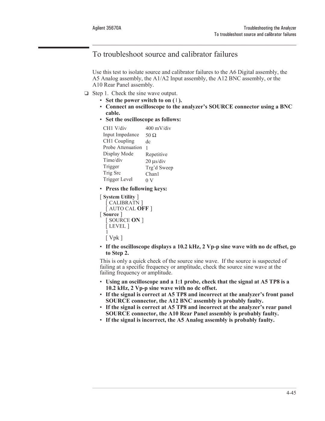
To troubleshoot source and calibrator failures
Connect the voltmeter to A5 TP3 Press the following keys
Assembly is
Oscilloscope Setup Parameters Waveform
Check the calibrator output
Press LOW Level CAL
Press the following keys
Check the Input assembly
Set the frequency synthesizer as follows
Test Location Amplitude 10% Probable Faulty Assembly
To troubleshoot input and ADC failures
To troubleshoot input and ADC failures
Enter numbers between 127 and +128
Set the oscilloscope to 700 mV/div
To troubleshoot input failures on four channel analyzers
Exchange the Input assemblies
Assembly that failed is probably faulty
‘’Verifying Specifications.’’
To troubleshoot distortion failures
Guides at the sides of the card nest
To troubleshoot disk drive failures
New formatted disk and repeat the previous step
To troubleshoot auto-range failures
Set the power switch to on l Press the following keys
Inst Mode
Range should be set to 5 dBVrms
To troubleshoot DIN connector failures
Trigger
To troubleshoot trigger failures
Meas Data
Press EXT Range +
Change the frequency synthesizer’s amplitude to 0.3 Vp-p
Trigger Mode Failing Probable Faulty Assembly or Next Step
Agilent 35670A
Check external trigger signal to the Analog assembly
To troubleshoot memory battery failures
To troubleshoot memory battery failures
To troubleshoot microphone power and adapter failures
To troubleshoot tachometer failures
Oscilloscope Setup Parameters
Press TRG Range +
With 2 ±0.2 Vdc offset
Page
Adjusting the Analyzer
Adjustment Assembly Component
Adjusting the Analyzer
Operator controls inside the analyzer
Potentially dangerous voltages
Remote Operation
Adjustment Gpib Code
Equipment Required Frequency Counter
To adjust the frequency reference
Equipment Required Multimeter
To adjust the source
Equipment Required Oscilloscope
To adjust the ADC gain, offset and reference
Set the oscilloscope as follows
Adjust A5 R407 for a flat trace on the oscilloscope
Service Tests Adjustmts ADC Adjustmnt Offset
Equipment Required None
To adjust the input dc offset
Set the power switch to on Press the following keys
Channel 3 Adjustmnt Offset
Equipment Required BNC-to-BNC Cable
To adjust common mode rejection
Service Tests Adjustmts Channel 1 Adjustmnt Cmrr
Channel 3 Adjustmnt Cmrr
Channel 4 Adjustmnt Cmrr
To adjust filter flatness
Rtn Channel 2 Adjustmnt 50 kHz Flatness
Channel 1 Adjustmnt 50 kHz
Rtn Channel 2 Adjustmnt 25 kHz Flatness
Channel 1 Adjustmnt 25 kHz
Rtn Channel 4 Adjustmnt 25 kHz Flatness
Rtn Channel 3 Adjustmnt 25 kHz Flatness
To adjust the display voltage
To adjust the display voltage
Replacing Assemblies
Replacing Assemblies
What to do before replacing the CPU assembly
What to do after replacing an assembly
A9 Nvram
To remove cover
To remove rear panel
To remove front panel
To remove front panel
To remove disk drive
To remove CPU
To remove Nvram
To remove memory
To remove power supply
Replacing Assemblies
To remove motherboard
To remove motherboard
To remove dc-dc converter
Replaceable Parts
Non-Listed Parts
Ordering Information
Mfr No Mfr Name Address
Direct Mail Order System
Code Numbers
Assemblies
Agilent Part
Agilent Part Qty Description Mfr Mfr Part Number Code
Cables
Instrument Covers and Handles
Assembly Covers and Brackets
RFI STRIP-FINGERS BE-CU Bright DIP
Front Panel Parts
Rear Panel Parts
Chassis Parts
Miscellaneous Parts
Screws, Washers, and Nuts
Option UK4 Parts
Replaceable Parts Agilent 35670A Option UK4 Parts
Circuit Descriptions
Overall Instrument Description
Circuit Descriptions
Nvram
BNC
CPU
Overall Instrument Description
Two Channel Overall Block Diagram
Four Channel Overall Block Diagram
A1 Input
Agilent 35670A
A1 Input Block Diagram Channel
Agilent 35670A Circuit Descriptions A1 Input
A1 Input Block Diagram Channel
A1 Input Block Diagram Channel
A2 Input
A2 Input
A2 Input Block Diagram Channel 1 or Channel
Agilent 35670A Circuit Descriptions A2 Input
A2 Input Block Diagram Channel 3 or Channel
A2 Input Block Diagram Channel 3 or Channel
A5 Analog
A5 Analog Block Diagram ADC and Trigger
Trigger-Level Input
A5 Analog Block Diagram Analog Source and Calibrator
A6 Digital
ADC timing and synchronization signals
A6 Digital Block Diagram
RAM
Fifo RAM
A7 CPU
A7 CPU Block Diagram
A7 CPU Block Diagram Interface
Reset Logic
Disk Controller Display Controller Frame Memory
Disk Utility
A8 Memory
A8 Memory
A9 Nvram
A9 Nvram Block Diagram
DAC
A10 Rear Panel
A10 Rear Panel Block Diagram
A11 Keyboard Controller
A11 Keyboard Controller Block Diagram
A12 BNC
A15 Primary Keypad
A13 Primary Keypad
A14 Secondary Keypad
A90 Fan
A98 Power Supply
A100 Disk Drive
A99 Motherboard
A101 Display
A102 DC-DC Converter
Option UK4 Microphone Adapter and Power Supply
Option UK4 Microphone Adapter and Power Supply Block Diagram
Page
Voltages and Signals
Section Title Describes signals routed
Voltages and Signals
Assembly Locations
Assembly Locations and Connections
Assembly Connections for Two Channel Analyzer
Assembly Connections for Four Channel Analyzer
From Path Voltages
Power Supply Voltage Distribution
A2 Input
A1 Input
A7 J3 Pins A8 P1 Pins
PA7
Flashen
Memreset
G20MHZ
PRW
SIZE0 SIZE1
A9 Nvram
Vbatt
ATN
A10 Rear Panel
DIO1 DIO8
Serial Port
DSR
DTR
Select
Parallel Port
Busy
Source Output
DIN Keyboard
Tachometer Input
External Trigger Input
A11 Keyboard Controller
A11 Keyboard Controller assembly
A12 BNC
Chanb COL0 COL7
Signal Name A11 Location
Chana
ROW0 ROW6
Voltages and Signals Agilent 35670A A13 Primary Keypad
Pwrfw
COL0 COL2
ROW0 ROW5
A22 BNC
Signal Name Assembly Using Signal
A99 Motherboard
23A
A99 Motherboard
Addata
A10MHZ
B5MHZ
Btach
FAN+
Extrgin
Fanful
Fanoff
H20MHZ
H10MHZ
Hsync
Imode
Prefs
Lpfclk
Pvalid
RRW
Srcdata
Srcclock
Syscntr
Trigger
A100 Disk Drive
Hdsel
DIR
SEL0 SEL1
Wdata
Vsyncel
Vclk
VID
Pins A7 P2 A102
Page
Internal Test Descriptions
High-level Subtests
Power-on Test Description
Low-level Subtests
Binary to Hexadecimal
Power-on Test Messages
Assembly/Sub-block Hexadecimal Message Code
Power-on Test Messages
Calibration Routine Description
DC-Offset Tables and Frequency Correction Curves
Viewing the Calibration Correction Curves
Calibration Error Messages
Active Trace
Disp Format
Active Trace Scale
Bootrom
Fault Log Messages
Self-Test Descriptions
Functional Tests All Self-Test Group
Assembly Softkey Self Test Name A12 A10 A11 A100 A22
Self Test Front Panel Softkey
Self Tests that Perform a Measurement
Dgtl Srce Thru
Individual Self-Test Descriptions
Fast BUS
Long Conf Test
Random Seek
Serial Port
Self Test Gpib Command
Self-Test Menu Map and Gpib Commands
Self Test Functionl Tests Digital Processor Trigger
Page
Backdating
Backdating
Quick Reference
Quick Reference
12-3
Quick Reference Agilent 35670A
12-5
Quick Reference
12-7
12-8
12-9
12-10
12-11
12-12
12-13
A2 Input Block Diagram Channel 2 or Channel
12-15
12-16
12-17
12-18
12-19
12-20
121 12-21
A8 Memory Block Diagram
12-23
12-24
12-25
12-26
Index
Cleaning the screen
10-14
9-34
Cross talk test
Troubleshooting four channels Installation
Controller Self-test description 10-14 Signals 8-29
10-9
10-15
Phone assistance
10-12
10-17
10-10 10-16
10-18
Zoom self test
If you are thinking about You want to Then read
Guide to Agilent 35670A Documentation
Need Assistance?
About this edition