Scanner and Scanner/Scale Nomenclature
Connectors
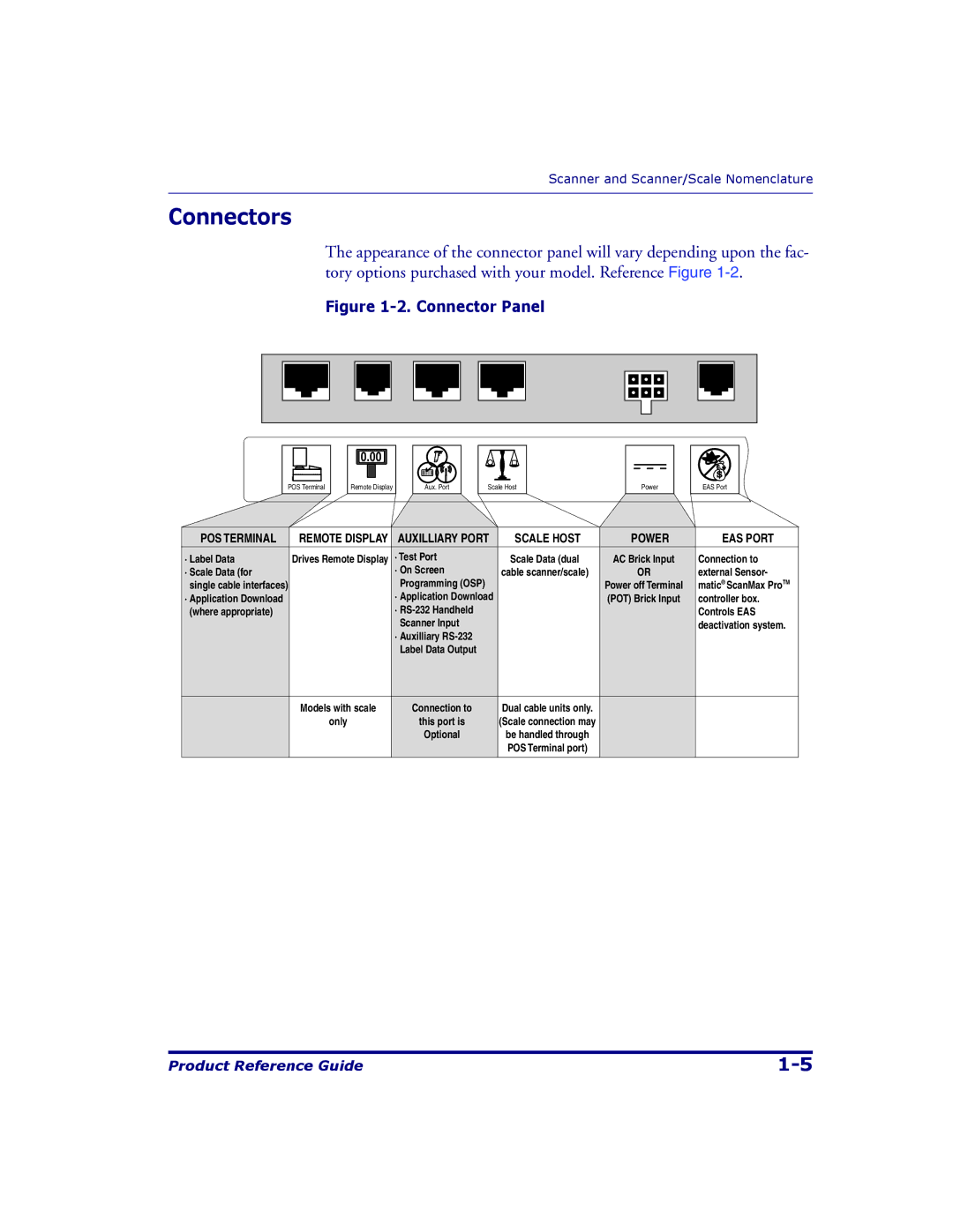
The appearance of the connector panel will vary depending upon the fac- tory options purchased with your model. Reference Figure
Figure 1-2. Connector Panel
POS Terminal
0.00
Remote Display
Aux. Port
Scale Host
Power
EAS Port
POS TERMINAL | REMOTE DISPLAY | AUXILLIARY PORT | SCALE HOST | POWER | EAS PORT |
· Label Data | Drives Remote Display | · Test Port | Scale Data (dual | AC Brick Input | Connection to |
· Scale Data (for |
| · On Screen | cable scanner/scale) | OR | external Sensor- |
single cable interfaces) |
| Programming (OSP) |
| Power off Terminal | matic® ScanMax ProTM |
· Application Download |
| · Application Download |
| (POT) Brick Input | controller box. |
(where appropriate) |
| · |
|
| Controls EAS |
|
| Scanner Input |
|
| deactivation system. |
|
| · Auxilliary |
|
|
|
|
| Label Data Output |
|
|
|
|
|
|
|
|
|
| Models with scale | Connection to | Dual cable units only. |
|
|
| only | this port is | (Scale connection may |
|
|
|
| Optional | be handled through |
|
|
|
|
| POS Terminal port) |
|
|
|
|
|
|
|
|
Product Reference Guide |