4.Disconnect the Load Cell harness.
5.Move the Load Cell/Spider Assembly into position on the opposite side of the scanner cavity and
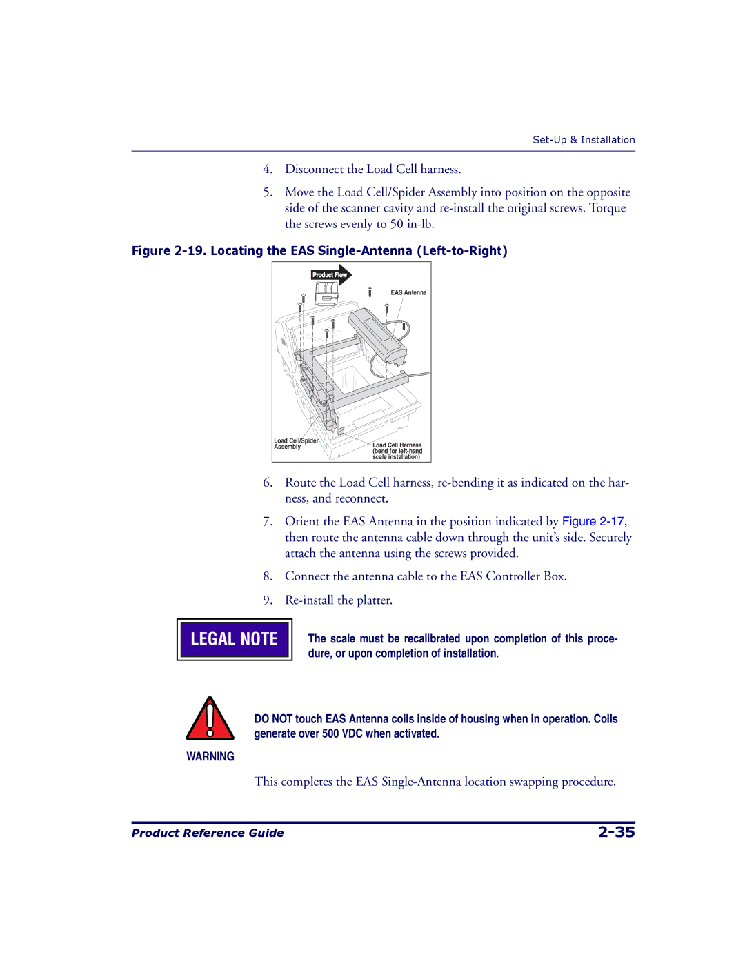
Figure 2-19. Locating the EAS Single-Antenna (Left-to-Right)
Product Flow |
|
| EAS Antenna |
Load Cell/Spider | Load Cell Harness |
Assembly | |
| (bend for |
| scale installation) |
6.Route the Load Cell harness,
7.Orient the EAS Antenna in the position indicated by Figure
8.Connect the antenna cable to the EAS Controller Box.
9.

 LEGAL NOTE
The scale must be recalibrated upon completion of this proce- dure, or upon completion of installation.
DO NOT touch EAS Antenna coils inside of housing when in operation. Coils generate over 500 VDC when activated.
WARNING
This completes the EAS
Product Reference Guide |