Controls and Indicators
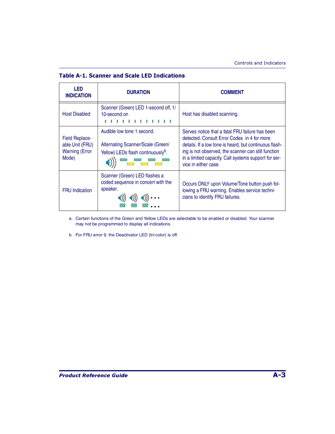
Table A-1. Scanner and Scale LED Indications
LED |
|
| DURATION | COMMENT | ||
INDICATION |
|
| ||||
|
|
|
|
|
| |
|
|
|
|
|
|
|
|
|
|
|
|
|
|
| Scanner (Green) LED |
| ||||
Host Disabled | Host has disabled scanning. | |||||
|
|
|
|
|
|
|
| Audible low tone 1 second. | Serves notice that a fatal FRU failure has been | ||||
Field Replace- |
|
|
|
|
| detected. Consult Error Codes in 4 for more |
able Unit (FRU) | Alternating Scanner/Scale (Green/ | details. If a low tone is heard, but continuous flash- | ||||
Warning (Error | Yellow) LEDs flash continuouslyb. | ing is not observed, the scanner can still function | ||||
Mode) |
|
|
|
|
| in a limited capacity. Call systems support for ser- |
|
|
|
|
|
| vice in either case. |
|
|
|
|
|
| |
|
|
|
|
|
|
|
| Scanner (Green) LED flashes a |
| ||||
| coded sequence in concert with the | Occurs ONLY upon Volume/Tone button push fol- | ||||
FRU Indication | speaker. | lowing a FRU warning. Enables service techni- | ||||
|
|
|
|
|
| cians to identify FRU failures. |
|
|
|
|
|
| |
|
|
|
|
|
|
|
a.Certain functions of the Green and Yellow LEDs are selectable to be enabled or disabled. Your scanner may not be programmed to display all indications.
b.For FRU error 9, the Deactivator LED
Product Reference Guide |
