Set-Up & Installation
These setup and installation procedures assume that you have already pre- pared your checkstand to receive the scanner or scanner/scale. If you have not already made the counter cutout and routed power and interface cables, do so now as described in the previous instructions. If your check- stand has been prepared, proceed as follows:
EAS Considerations
When installing a system which includes EAS deactivation, issues to be considered are:
•Placement of the EAS Controller Box. The controller must be located near the scanner, and be within easy connection of an ade- quate power supply.
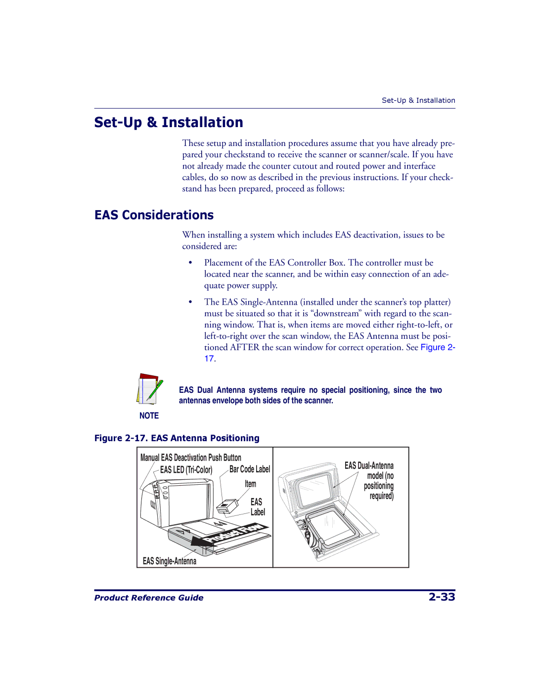
•The EAS
EAS Dual Antenna systems require no special positioning, since the two antennas envelope both sides of the scanner.
NOTE
Figure 2-17. EAS Antenna Positioning
Manual EAS Deactivation Push Button | EAS | ||
EAS LED | Bar Code Label | ||
model (no | |||
| Item | ||
| positioning | ||
| EAS | required) | |
|
| ||
| Label |
| |
EAS |
|
| |
Product Reference Guide |