State/State
Mixed Mode
Display
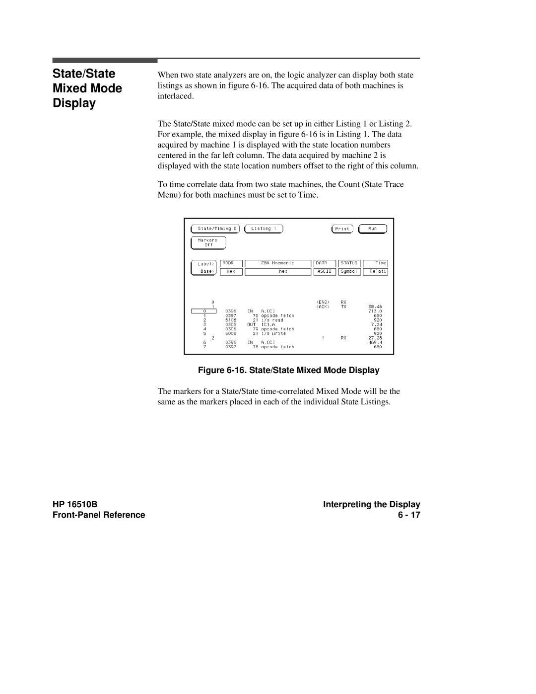
When two state analyzers are on, the logic analyzer can display both state listings as shown in figure
The State/State mixed mode can be set up in either Listing 1 or Listing 2. For example, the mixed display in figure
To time correlate data from two state machines, the Count (State Trace Menu) for both machines must be set to Time.
Figure 6-16. State/State Mixed Mode Display
The markers for a State/State
HP 16510B | Interpreting the Display |
6 - 17 |