5Specify Symbols
Menus 5-14
You enter a threshold in the
In the state analyzer, the same threshold level applies to a pod’s clock as to its 16 data bits.
The logic analyzer supplies Timing and State Symbol Tables in which you can define a mnemonic for a specific bit pattern of a label. When measurements are made by the logic analyzer, the mnemonic is displayed where the bit pattern occurs if the Symbol base is selected.
It is possible for you to specify up to 200 symbols in the logic analyzer. If you have only one of the internal analyzers on, all 200 symbols can be defined in it. If both analyzers are on, the 200 symbols are split between the two. For example, analyzer 1 may have 150, leaving 50 available for analyzer 2.
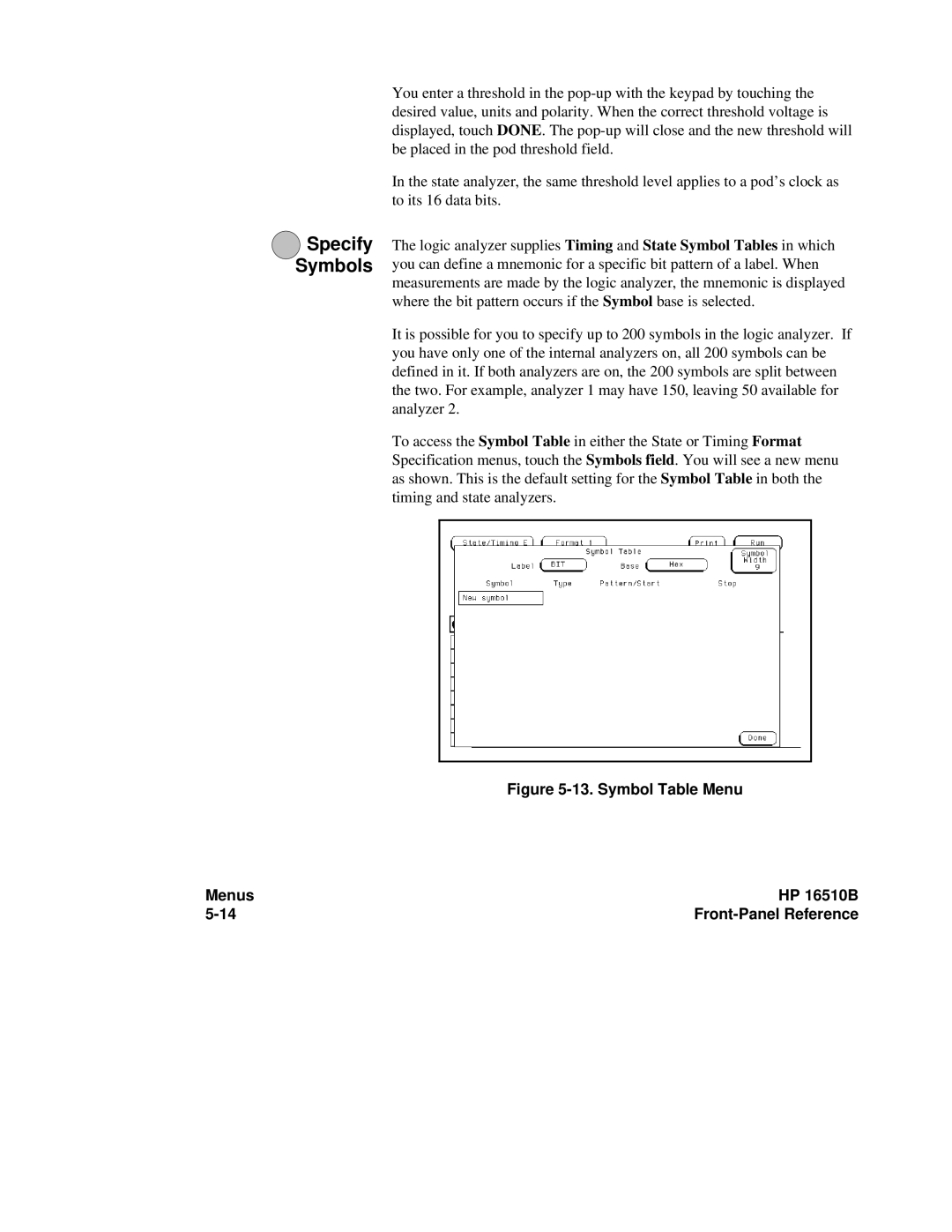
To access the Symbol Table in either the State or Timing Format Specification menus, touch the Symbols field. You will see a new menu as shown. This is the default setting for the Symbol Table in both the timing and state analyzers.