Delay Field
The delay field allows you to enter a delay. The delay can be either positive or negative. Delay allows you to place the time window (selected by s/Div) of the acquired data at center screen.
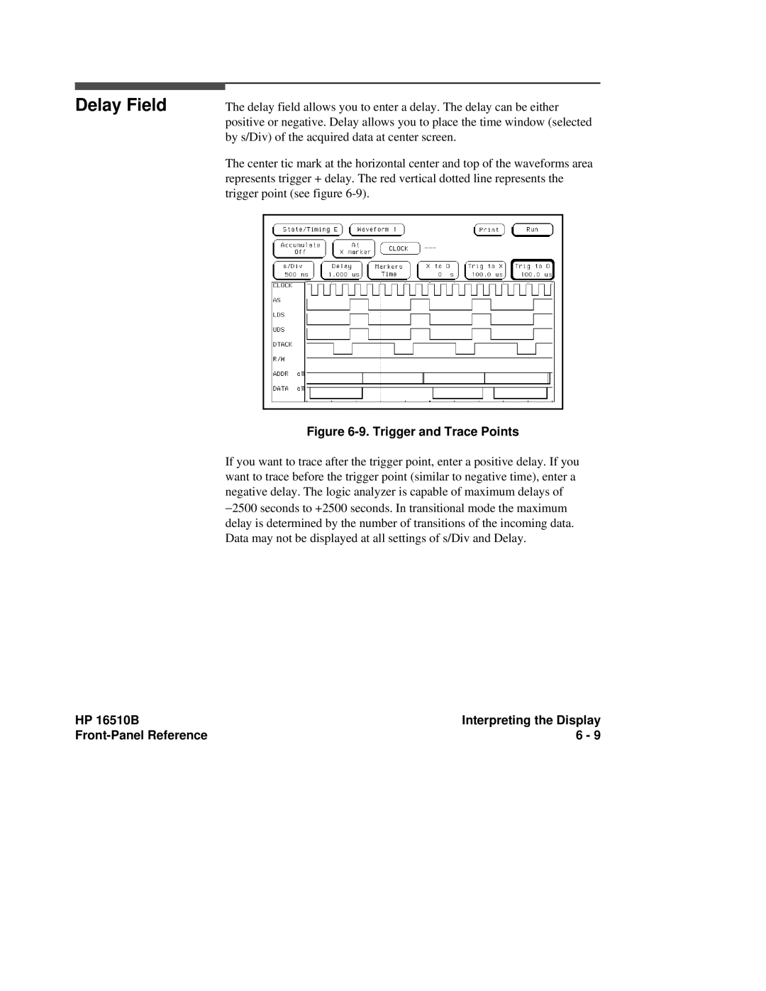
The center tic mark at the horizontal center and top of the waveforms area represents trigger + delay. The red vertical dotted line represents the trigger point (see figure
Figure 6-9. Trigger and Trace Points
If you want to trace after the trigger point, enter a positive delay. If you want to trace before the trigger point (similar to negative time), enter a negative delay. The logic analyzer is capable of maximum delays of −2500 seconds to +2500 seconds. In transitional mode the maximum delay is determined by the number of transitions of the incoming data. Data may not be displayed at all settings of s/Div and Delay.
HP 16510B | Interpreting the Display |
6 - 9 |