How Do I
Logic Analyzer?
Connecting the
Timing Analyzer
Probes
In order to make this measurement, you must
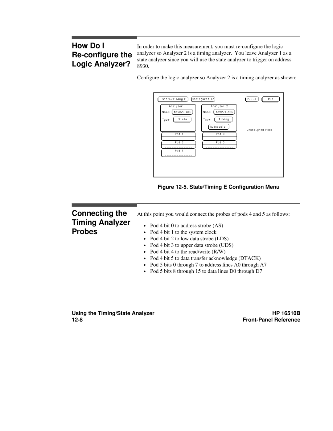
Configure the logic analyzer so Analyzer 2 is a timing analyzer as shown:
Figure 12-5. State/Timing E Configuration Menu
At this point you would connect the probes of pods 4 and 5 as follows:
∙Pod 4 bit 0 to address strobe (AS)
∙Pod 4 bit 1 to the system clock
∙Pod 4 bit 2 to low data strobe (LDS)
∙Pod 4 bit 3 to upper data strobe (UDS)
∙Pod 4 bit 4 to the read/write (R/W)
∙Pod 4 bit 5 to data transfer acknowledge (DTACK)
∙Pod 5 bits 0 through 7 to address lines A0 through A7
∙Pod 5 bits 8 through 15 to data lines D0 through D7
Using the Timing/State Analyzer | HP 16510B |
|
|