Connecting the Probes
At this point, if you had a target system with a 68000 microprocessor, you would connect the logic analyzer to your system. Since you have assigned labels ADDR and DATA, you would hook the probes to your system accordingly.
∙Pod 1 probes 0 through 15 to the data bus lines D0 through D15.
∙Pod 2 probes 0 through 15 to the address bus lines A0 through A15.
∙Pod 3 probes 0 through 7 to the address bus lines A16 through A23.
∙Pod 1, CLK (J clock) to the address strobe (LAS).
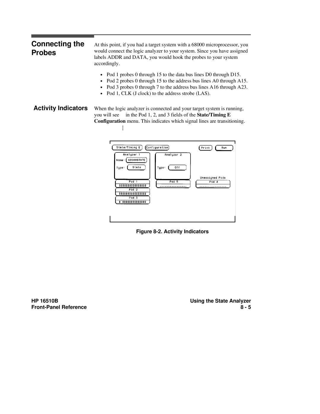
Activity Indicators When the logic analyzer is connected and your target system is running, you will see in the Pod 1, 2, and 3 fields of the State/Timing E Configuration menu. This indicates which signal lines are transitioning.
Figure 8-2. Activity Indicators
HP 16510B | Using the State Analyzer |
| 8 - 5 |