You can connect the probe directly to the test pins on your target system. To do so, the pins must be 0.63 mm (0.025 in.) square pins or round pins with a diameter of between 0.66 mm (0.026 in.) and 0.84 mm (0.33 in.).
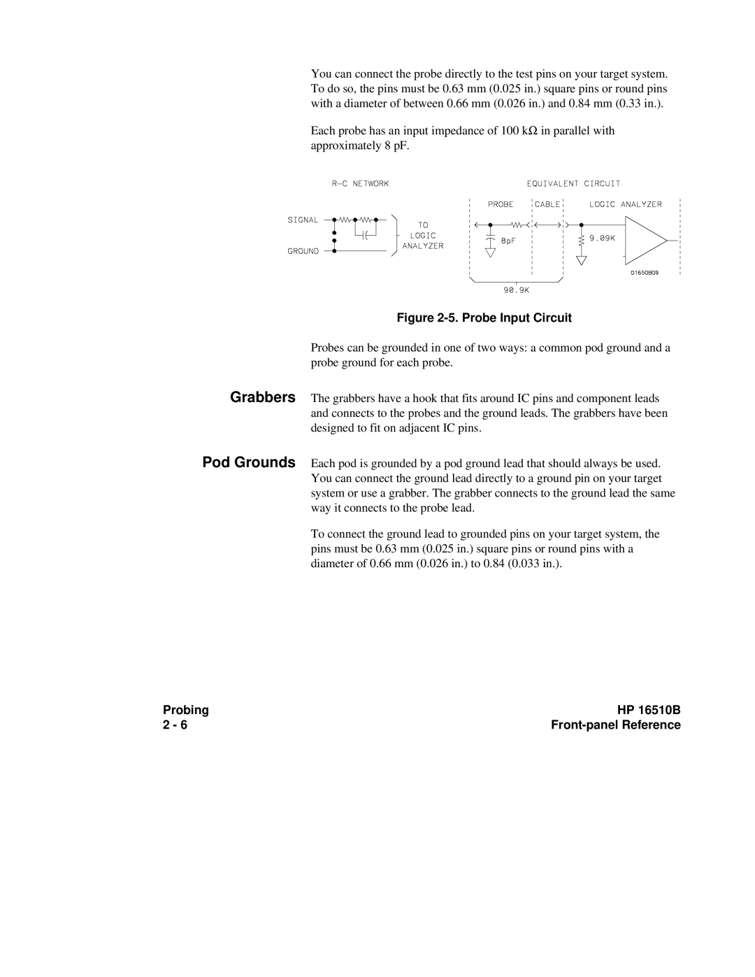
Each probe has an input impedance of 100 kΩ in parallel with approximately 8 pF.
Figure 2-5. Probe Input Circuit
Probes can be grounded in one of two ways: a common pod ground and a probe ground for each probe.
Grabbers The grabbers have a hook that fits around IC pins and component leads and connects to the probes and the ground leads. The grabbers have been designed to fit on adjacent IC pins.
Pod Grounds Each pod is grounded by a pod ground lead that should always be used. You can connect the ground lead directly to a ground pin on your target system or use a grabber. The grabber connects to the ground lead the same way it connects to the probe lead.
To connect the ground lead to grounded pins on your target system, the pins must be 0.63 mm (0.025 in.) square pins or round pins with a diameter of 0.66 mm (0.026 in.) to 0.84 (0.033 in.).
Probing | HP 16510B |
2 - 6 |