With these glitch detection fields you specify on which channel or channels you want the analyzer to look for a glitch. These fields are discussed in more detail in the "Then Find Edge" section later in this chapter.
Glitch Acquisition mode causes the storage memory to be cut in half, from 1k to 512. Half of the memory (512) is allocated for storing the data sample, and the other half for storing the second transition of a glitch in a sample. Every sample is stored. The sample rate varies from 20 Hz to 50 MHz (50 ms/sample to 20 ns/sample) and is automatically selected by the timing analyzer to insure complete data in the window of interest.
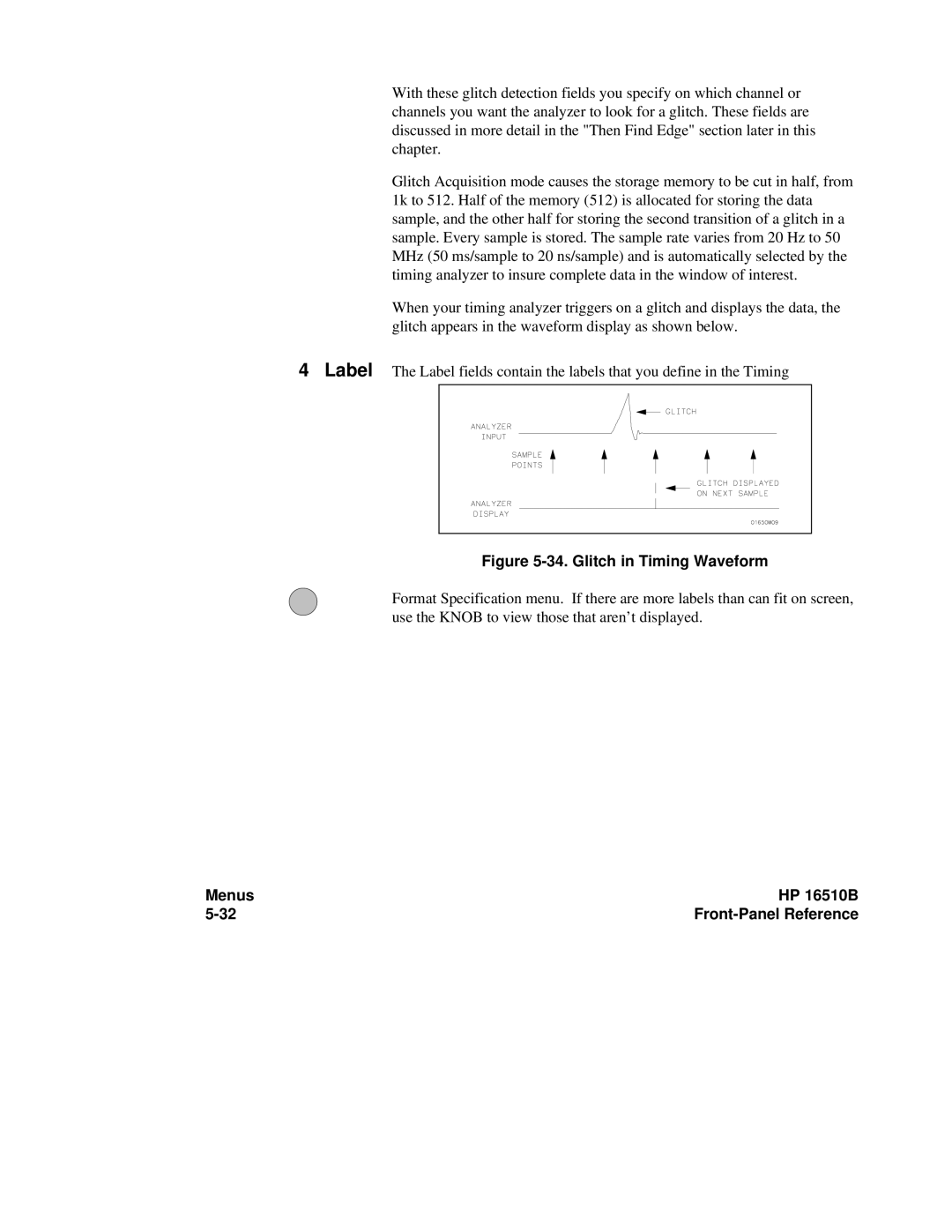
When your timing analyzer triggers on a glitch and displays the data, the glitch appears in the waveform display as shown below.
4Label The Label fields contain the labels that you define in the Timing
Figure 5-34. Glitch in Timing Waveform
Format Specification menu. If there are more labels than can fit on screen, use the KNOB to view those that aren’t displayed.
Menus | HP 16510B |
|
