Dc drives
Converter software version
Contents
Abbreviated Parameter List
Faults and Alarms
Start-up
Simplified Block Diagrams
Operating Instructions
Definitions
Qualified Personnel
Siemens Energy & Automation
Electro-statically sensitive devices
Siemens Energy & Automation
General Information
Base Drive Panel Description
Rated DC Current
Card Rack Assembly
US Rating Quad Type
Horsepower Amps DC Catalog No 240V DC 500V DC
Base Drive Panel Catalog Numbers
Spare Parts
Service
Technical Assistance
800-333-PIC1
EB1, EB2, SBP and SLB boards
Option Part Numbers
Options Order No
Spare Parts
Description Where Used Part Recom
Printed Circuit Boards
Cables
Fans/Blowers
Description Where Used Part Number Recom
Field Converter Diode Modules
Armature Converter Thyristor Modules, for 4-Quad Drives
Field Converter Thyristor Modules
Armature Converter DC Fuses, 4-Quad Only, 4PFU
Power Fuses Armature Converter AC Line Fuses, 1PFU 3 PFU
Control Transformer Primary Fuses 1CFU, 2CFU
Field Converter AC Line Fuses 1 & 2FSFU
Control Transformer Secondary Fuse 3CFU
Description
Main Contactor M
Control Transformer 1CTR, 2CTR, 3CTR
Contactor Coil Suppressor 1SP, Ensp
Auxiliary Relay, EN, and Rectifier Bridge, Mrec
Siemens Energy & Automation, Inc. Seller
Standard Terms and Conditions of Sale
Operating Instructions
Siemens Energy & Automation
Receiving, unpacking
Procedure for Shipping Damage
Siemens Energy & Automation
100
15ADC to 100ADC Base Drive Panels, 3AC 460V, 1 & 4Q
140 210 255 430 510 850
140ADC to 850ADC Base Drive Panels, 3AC 460V, 1 & 4Q
1180 1660 1680
Ambient temperature Reduction in base drive dc ampere rating
Applicable standards
Siemens Energy & Automation
Installation Information
Installation and Dimensions
15 30 AMP Base Drive PANELS, 1 & 4Q
Dimensions are mm inches
Base Drive Panel Outlines
AMP Base Drive PANEL, 1 & 4Q
Terminals 80 Power Terminals
L1 L2 L3 A1 A2
1120 44.1 1100 43.3
AMP Base Drive PANEL, 1 & 4Q
AMP Base Drive PANEL, 1 & 4Q
280 11.0 1200 47.2
740 29.1
965 38.0
AMP Base Drive PANEL, 1 & 4Q
965 38.0
Siemens Energy & Automation
Base Drive Panel Connections
Base Drive PANEL, 15 AMPS, 1 & 4 Quad
Base Drive Panel Schematics
Base Drive PANEL, 30 AMPS, 1 & 4 Quad
Base Drive PANEL, 60 AMPS, 1 & 4 Quad
Base Drive PANEL, 100 AMPS, 1 & 4 Quad
INCH- LBS
Base Drive PANEL, 140 AMPS, 1 & 4 Quad
Base Drive PANEL, 210 AMPS, 1 & 4 Quad
Base Drive PANEL, 255 AMPS, 1 & 4 Quad
1CTR
Base Drive PANEL, 430 AMPS, 1 & 4 Quad
Base Drive PANEL, 510 AMPS, 1 & 4 Quad
Base Drive PANEL, 850 AMPS, 1 & 4 Quad
3CTR
Base Drive PANEL, 1180 AMPS, 1 & 4 Quad
2CTR 3CTR
Base Drive PANEL, 1660 AMPS, 1 & 4 Quad
Catalog no RA7096-4GV62-0Z+X01, 4-QUAD
Base Drive PANEL, 1680 AMPS, 1 & 4 Quad
Operating Instructions
CUD
Control Connections CUD1
Terminal Locations CUD1
Optional CUD2 Control Connections
Control Connections CUD2
Terminal Locations CUD2
Base Drive Panel Power Connections 15 to 100 Amp
Description of Power/Control Terminals
Base Drive Panel Power Connections 430 to 1680 Amp
Function Terminal Connection values/Remarks Possible
Motor Armature circuit
Internally connected to incoming 460 VAC, 3 Phase
Siemens Energy & Automation
Start-Up
General safety information for start-up
Simple operator control panel PMU Parameterization Unit
Operator control panels
LED displays
User-friendly operator control panel OP1S
Parameterization on simple operator control panel
Parameterization procedure
Parameter types
Operating Instructions
A1+ A2- 80+
Typical Connection Diagrams
PMU
Speed
Execution of the default function
Reset to factory default values and adjust offsets
Panels
Start-up procedure
Adjustment of converter rated currents
Access authorization
Adjustment to actual converter supply voltage
Input of motor data
Operation with pulse encoder
Freely wired actual value
Pulse encoder type Normal selection
Operation without tachometer EMF control
Selection of basic technological functions
Field data
Execution of optimization runs
Siemens Energy & Automation
Operating Instructions
Setting Application Functions
Checking and possible fine adjustment of maximum speed
Source of Start Command P654 =
Starting the Drive
Source of Speed Setpoint P433 =
Speed Setpoint Selection
Source of Jog Setpoint P436 = Value
Jog Inching Configuration
Source of Jog Command P435 = Value
Documentation of setting values
Siemens Energy & Automation
On the OP1S
Fault messages
General information about faults
Further information about the causes of fault messages
List of fault messages
2.1 Supply faults
F001 Failure of electronics power supply
P078.001 ∗ 100%P353
Fault Description
F007 Overvoltage
F006 Undervoltage
Parameter P363
Interface error
F011 Telegram failure at GSST1
USS telegram failure at G-SST1
USS telegram failure at G-SST2
F012 Telegram failure at GSST2
Peer-to-peer telegram failure at G-SST2
F013 Telegram failure at GSST3
F016 Hardware fault on expansion board EB1
External faults
F017 Hardware fault on expansion board EB2
F015 Telegram failure on one Simolink board
F021 External fault
Fault messages from motor sensors
F022 External fault
F023 Fault message from free function block FB2
F029 Motor overtemperature active in all operating states
Drive faults
P493=2 or 3 temperature sensor at terminals 22 / 23 or
P494=2 or 3 temperature sensor at terminals 204
F038 Overspeed
F034 Fault message from free function block FB5
F035 Drive is blocked
Cause as a function of fault value
F042 Tachometer fault
Fault Description
F050
Start-up faults
Fault Description
Fault Description
Fault Description
Fault Description
V2.1 and later
F051 No optimization run when permanent memory is disabled
F056 Important parameter is not set
F058 Parameter settings are not consistent
Operating Instructions
Hardware faults
R047 Index 002 to
Internal faults
Number of faulty parameter
F064 Watchdog timer has initiated a reset
Fault
F067 Converter cooling faulty
F063
F069 Mlfb data are faulty active in all operating states
Communication errors with supplementary boards
F081 CB/TB heartbeat error
F080 Error in initialization of a CB/TB board
F082 CB/TB message timeout or error in data exchange
F078
F101 to F147
Fault messages from supplementary boards
Alarm messages
A028 Motor overtemperature active in all operating states
Alarm Description A025 Brush length too short
A029 Motor overtemperature active in all operating states
A026 Poor bearing condition active in all operating states
A039 I2t value of power section too high
A034 Alarm message from free function block FB9
A047 Analog select input 1 terminals 6 and 7 faulty
A035 Drive blocked
A053 Alarm message from free function block FB258
Alarm Description A049 SCB1 No SCI slave connected
A054 Alarm message from free function block FB259
A067 Converter cooling faulty
Siemens Energy & Automation
Simoreg DC Master Base Drive Panel Operating Instructions
Overview
10-1
Range of parameter numbers Function
10-2
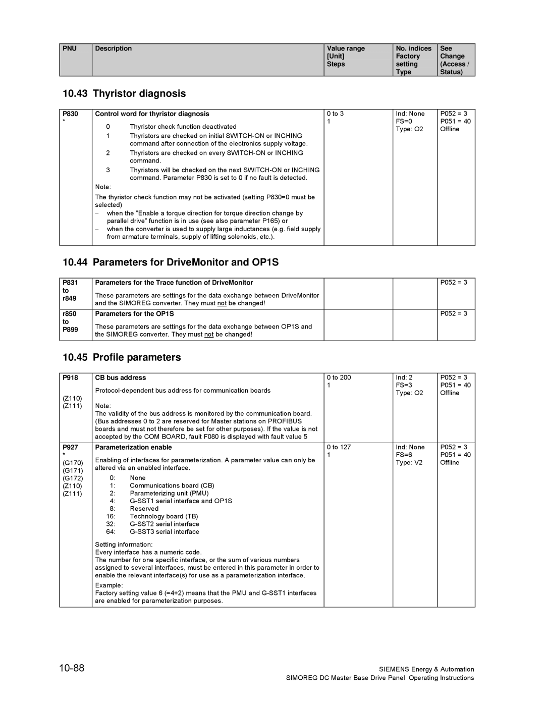
P899 Parameters for DriveMonitor and OP1S
R999
S00
Overview of abbreviations
10-3
10-4
10-5
Operating status display
10-6
10-7
General visualization parameters
10-8
10-9
10-10
10-11
Access authorization levels
10-12
10-13
Definition of Simoreg DC Master converter
R065 Software identifiers
10-14
P067 Load class
R068 Options according to rating plate
10-15
P077 Total thermal reduction factor
10-16
Temp = k1
P078 Reduction of converter rated supply voltage
10-17
Setting values for converter control
P080 Control word for brake control
P081 EMF-dependent field weakening
External field power module 40.00A field
Internal field power module
10-18
No field
10-19
P085 Wait period after cancellation of inching command
P086 Voltage failure period for automatic restart
P087 Brake release time
P091 Setpoint threshold
10-20
P090 Stabilization time for line voltage
P094 Switch-off delay for auxiliaries
P093 Pick-up delay for line contactor
10-21
P095 Pick-up time for a contactor in the DC circuit
10-22
Definition of motor
10-23
10-24
Magnetization characteristic field characteristic
10-25
10-26
Example of a field characteristic
10-27
10-28
P142 Matching to pulse encoder signal voltage
Single/multiple evaluation of encoder pulses
P140 Selection of pulse encoder type
Rev/min FS=500.0 P051 G145 1rev/min Type O4 Online 100%
P144 Multiple evaluation of encoder signals
10-29
10-30
10-31
10-32
Current limitation, torque limitation
10-33
10-34
Auto-reversing stage, armature gating unit
Speed controller
10-35
10-36
Closed-loop field current control, field gating unit
10-37
10-38
Closed-loop EMF control
Ramp-function generator
P295 Mode for rounding the ramp-function generator
10-39
P296 Ramp-down time of ramp generator with quick stop OFF3
10-40
10-41
Setpoint processing
10-42
Setting values for monitoring functions and limits
10-43
Setting values for limit-value monitors
10-44
10-45
Settable fixed values
10-46
Fixed control bits
10-47
10-48
Position sensing with pulse encoder
10-49
Connector selector switches
Motorized potentiometer
10-50
10-51
Oscillation
Definition of Motor interface
P496 Bearing condition Tripping of alarm or fault message
Tripping of alarm or fault message
P497 Air flow Tripping of alarm or fault message
P498 Temperature switch Tripping of alarm or fault message
10-53
Configuring of torque shell input
Speed limiting controller
10-54
Friction compensation
10-55
Compensation of moment of inertia dv/dt injection
Speed controller adaptation
10-56
P550 Gain in the adaptation range
P551 Integration time in the adaptation range
10-57
10-58
Input quantities for signals
Field reversal
10-59
Configuring of closed-loop control
Speed limiting controller . Both values are added
10-60
P602 Source for armature current controller actual value
Actual value
P605 Source for variable positive torque limit
10-61
P606 Source for variable negative torque limit
P607 Source for torque setpoint for master drive
10-62
10-63
10-64
10-65
10-66
10-67
Control word, status word
10-68
10-69
10-70
Further configuring measures
P690 Source for control word 2, bit30
P691 Source for control word 2, Bit31
10-71
P713 Mode of signal injection at Analog selectable input
P707 Resolution of Main setpoint analog input
10-72
P711 Normalization of Analog selectable input
10-73
10-74
10-75
Analog outputs
10-76
10-77
Binary outputs
10-78
Configuration of serial interfaces on basic converter
R789 Diagnostic information for G-SST1
See Change Access / Status P786 USS bus address for G-SST1
10-79
P787 Telegram failure time for G-SST1
P792 Length of parameter jobs for G-SST2
10-80
P793 Baud rate for G-SST2
Ind None P052 = Baud FS=6 P051 = G171 Type O2 Offline G173
10-81
See Change Access / Status P795 Options for G-SST2
P796 USS bus address for G-SST2
P797 Telegram failure time for G-SST2
Violation of telegram residual transfer time USS prot. only
10-82
P801 Number of process data for G-SST3
P802 Length of parameter jobs for G-SST3
10-83
See Change Access / Status P803 Baud rate for G-SST3
P804 Source for transmit data for G-SST3
P805 Options for G-SST3
P808
R809 Diagnostic information for G-SST3
10-84
10-85
See Change Access / Status R810 Receive data on G-SST1
R811 Transmit data on G-SST1
R812 Receive data on G-SST2
R815 Transmit data on G-SST3
10-86
10-87
Deactivation of monitoring functions
Compensation values
Parameters for DriveMonitor and OP1S
Thyristor diagnosis
Profile parameters
10-88
R947 Fault memory
Fault memory
R949 Fault value
R951 Fault text P952 Number of faults
10-90
Visualization parameters Alarms
10-91
Device identification
Visualization parameters Control and status word
R981 List of existing parameter numbers, continuation
R980 List of existing parameter numbers, start
R982 List of existing parameter numbers, continuation
R983 List of existing parameter numbers, continuation
10-93
10-94
Basic functions
Simplified block diagrams
Siemens Energy
Sheet 1 Legend
Setpoint System
Sheet 2 Speed
Controller and Current Limit
Sheet 3 Speed
Control
Sheet 4 Armature Current
Sheet 5 EMF and Field Current Control
11-6
Interface 1
Sheet 6 USS
USS interface
X172
Sheet 7 USS
Interface 2
Peer-to-peer interface
Sheet 8 Peer to Peer Interface
Exchange CB / TB to Base PZD
Sheet 9 Data
Control word
Sheet
Word
Sheet 11 Control
11-12
Status word
Status Word
Meaning
11-14
Sheet
Signals
Signals
Sheet 15 Miscellaneous
11-16
Siemens Energy & Automation, Inc