XS712T Smart Switch
The following table describes the Rapid STP Status information displayed on the screen.
Field | Description |
Interface | The physical or port channel interfaces associated with VLANs associated with |
| the CST. |
|
|
Role | Each MST Bridge Port that is enabled is assigned a Port Role for each spanning |
| tree. The port role will be one of the following values: Root Port, Designated |
| Port, Alternate Port, Backup Port, Master Port, or Disabled Port. |
|
|
Mode | Specifies the spanning tree operation mode. Different modes are STP, RSTP, |
| and MSTP. |
Fast Link | Indicates whether the port is enabled as an edge port. |
|
|
Status | The Forwarding State of this port. |
|
|
Click Refresh to update the information on the screen with the most current data.
MST Configuration
Use the Spanning Tree MST Configuration screen to configure Multiple Spanning Tree (MST) on the switch.
To configure an MST instance:
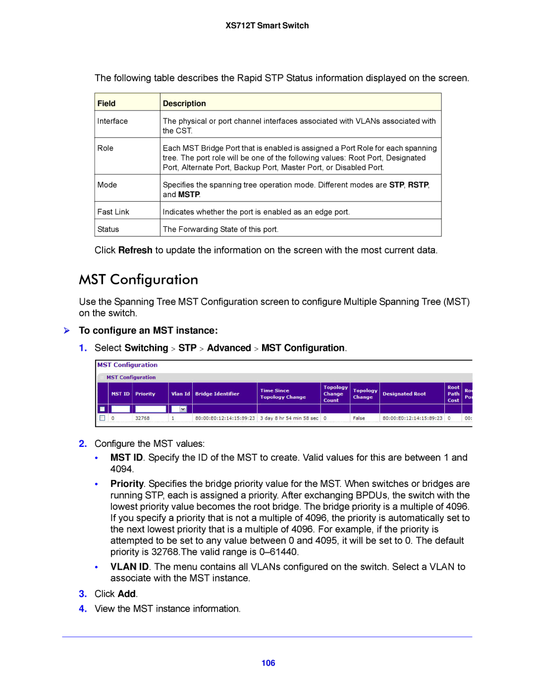
1.Select Switching > STP > Advanced > MST Configuration.
2.Configure the MST values:
•MST ID. Specify the ID of the MST to create. Valid values for this are between 1 and 4094.
•Priority. Specifies the bridge priority value for the MST. When switches or bridges are running STP, each is assigned a priority. After exchanging BPDUs, the switch with the lowest priority value becomes the root bridge. The bridge priority is a multiple of 4096. If you specify a priority that is not a multiple of 4096, the priority is automatically set to the next lowest priority that is a multiple of 4096. For example, if the priority is attempted to be set to any value between 0 and 4095, it will be set to 0. The default priority is 32768.The valid range is
•VLAN ID. The menu contains all VLANs configured on the switch. Select a VLAN to associate with the MST instance.
3.Click Add.
4.View the MST instance information.