XS712T Smart Switch
Sample MSTP Configuration
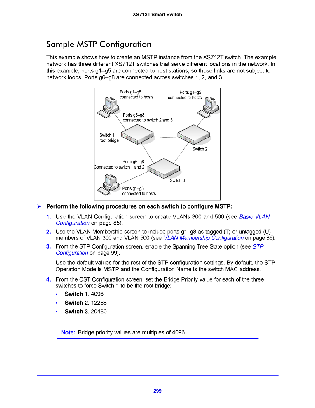
This example shows how to create an MSTP instance from the XS712T switch. The example network has three different XS712T switches that serve different locations in the network. In this example, ports
Ports | Ports |
connected to hosts | connected to hosts |
Ports
connected to switch 2 and 3
Switch 1 root bridge
Switch 2
Ports
Connected to switch 1 and 2
Switch 3
Ports
Perform the following procedures on each switch to configure MSTP:
1.Use the VLAN Configuration screen to create VLANs 300 and 500 (see Basic VLAN Configuration on page 85).
2.Use the VLAN Membership screen to include ports
3.From the STP Configuration screen, enable the Spanning Tree State option (see STP Configuration on page 99).
Use the default values for the rest of the STP configuration settings. By default, the STP Operation Mode is MSTP and the Configuration Name is the switch MAC address.
4.From the CST Configuration screen, set the Bridge Priority value for each of the three switches to force Switch 1 to be the root bridge:
•Switch 1. 4096
•Switch 2. 12288
•Switch 3. 20480
Note: Bridge priority values are multiples of 4096.