Introduction
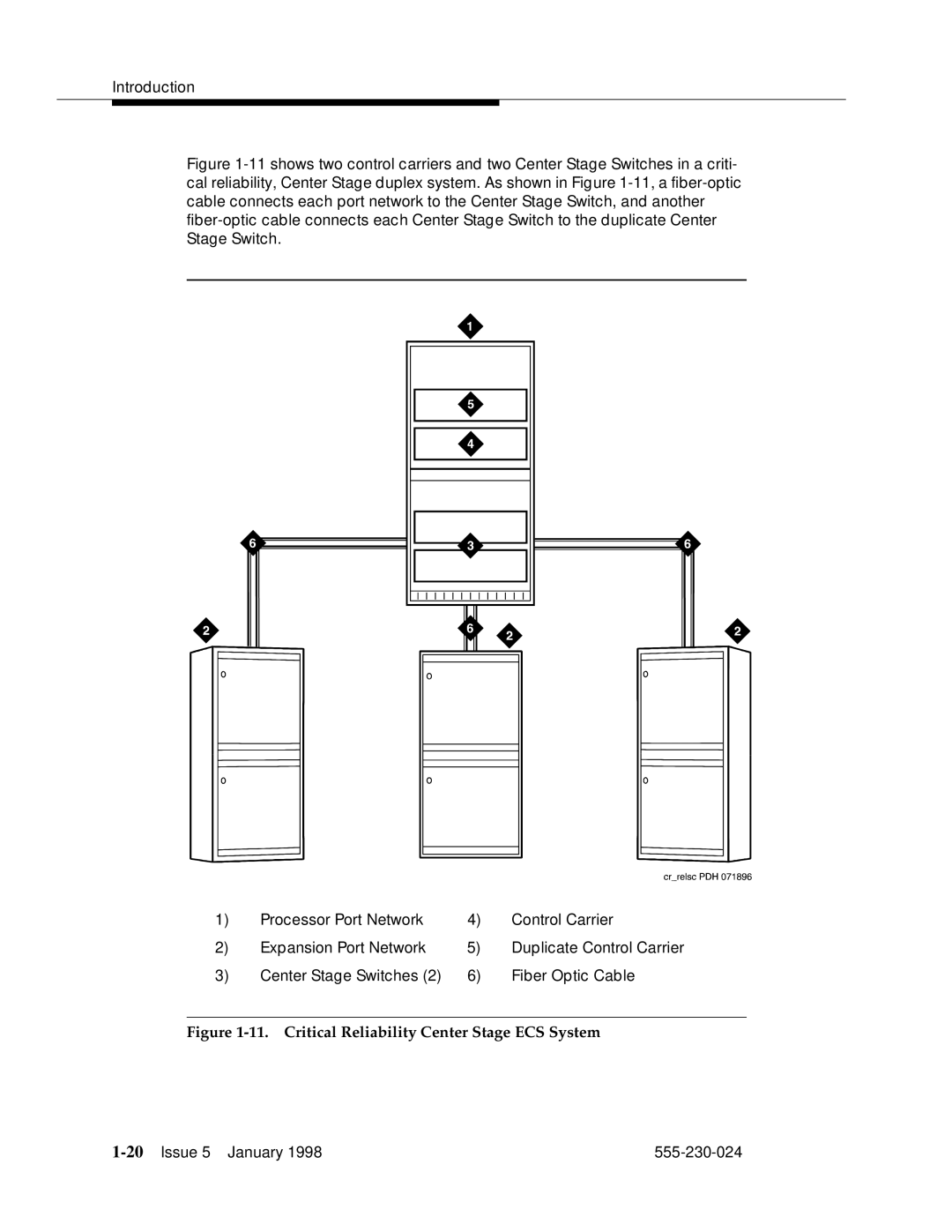
Figure 1-11 shows two control carriers and two Center Stage Switches in a criti- cal reliability, Center Stage duplex system. As shown in Figure 1-11, a fiber-optic cable connects each port network to the Center Stage Switch, and another fiber-optic cable connects each Center Stage Switch to the duplicate Center Stage Switch.
1) | Processor Port Network | 4) | Control Carrier |
2) | Expansion Port Network | 5) | Duplicate Control Carrier |
3) | Center Stage Switches (2) | 6) | Fiber Optic Cable |