5.3 Tabs
delete existing ones, as well as copy definitions from one connection blade to another.
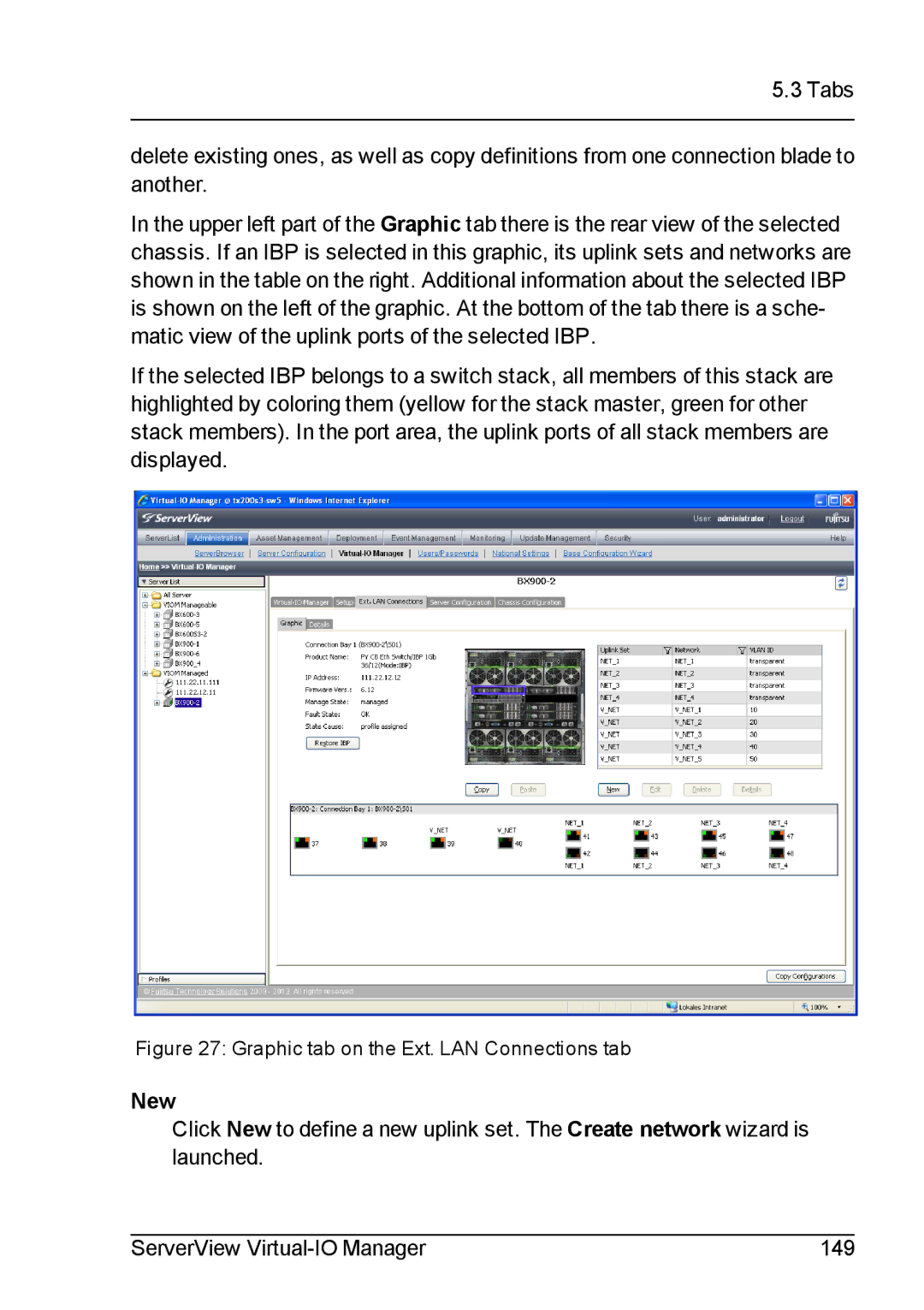
In the upper left part of the Graphic tab there is the rear view of the selected chassis. If an IBP is selected in this graphic, its uplink sets and networks are shown in the table on the right. Additional information about the selected IBP is shown on the left of the graphic. At the bottom of the tab there is a sche- matic view of the uplink ports of the selected IBP.
If the selected IBP belongs to a switch stack, all members of this stack are highlighted by coloring them (yellow for the stack master, green for other stack members). In the port area, the uplink ports of all stack members are displayed.
Figure 27: Graphic tab on the Ext. LAN Connections tab
New
Click New to define a new uplink set. The Create network wizard is launched.
ServerView | 149 |