5.3 Tabs
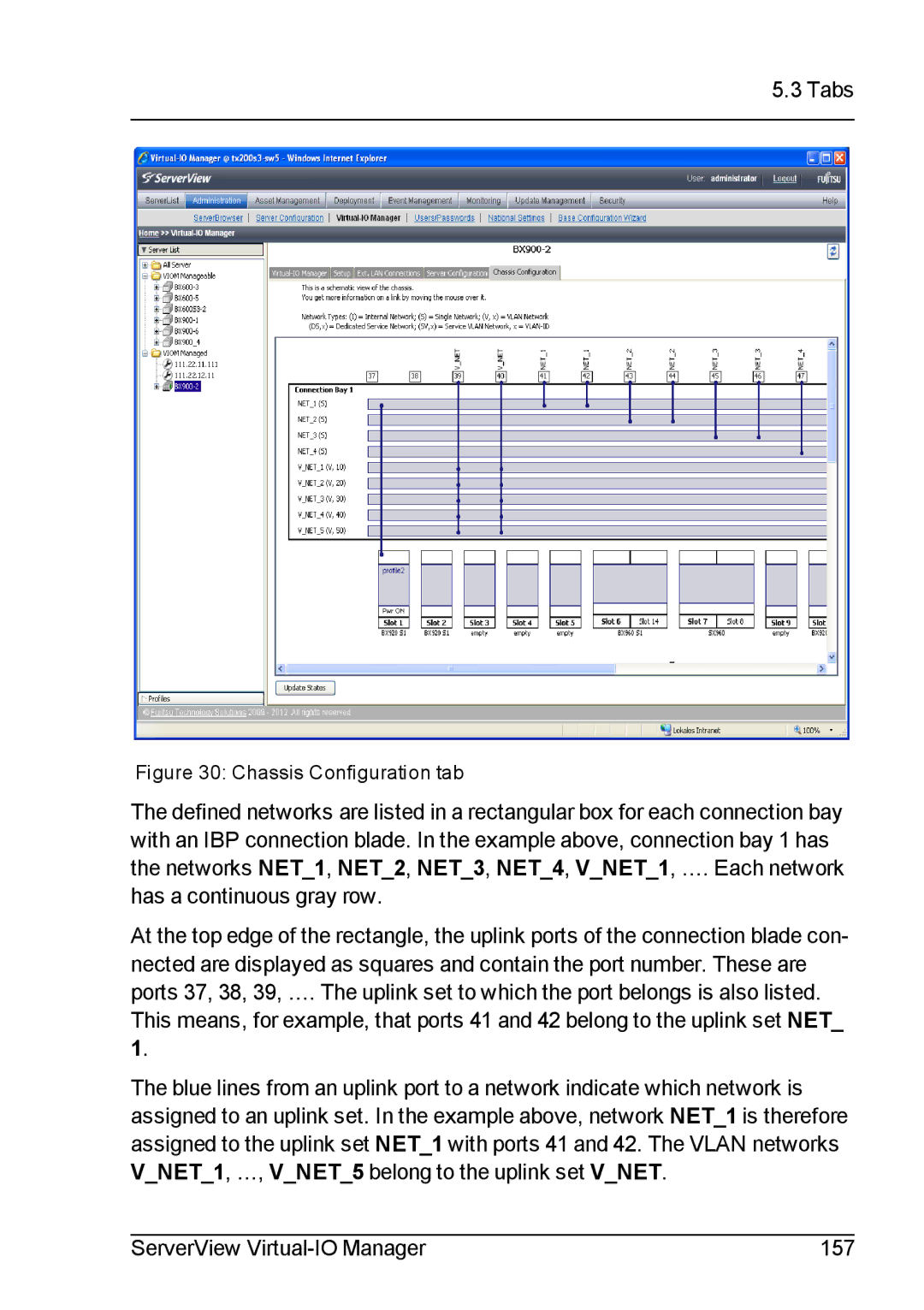
Figure 30: Chassis Configuration tab
The defined networks are listed in a rectangular box for each connection bay with an IBP connection blade. In the example above, connection bay 1 has the networks NET_1, NET_2, NET_3, NET_4, V_NET_1, …. Each network
has a continuous gray row.
At the top edge of the rectangle, the uplink ports of the connection blade con- nected are displayed as squares and contain the port number. These are ports 37, 38, 39, …. The uplink set to which the port belongs is also listed.
This means, for example, that ports 41 and 42 belong to the uplink set NET_ 1.
The blue lines from an uplink port to a network indicate which network is assigned to an uplink set. In the example above, network NET_1 is therefore assigned to the uplink set NET_1 with ports 41 and 42. The VLAN networks V_NET_1, …, V_NET_5 belong to the uplink set V_NET.
ServerView | 157 |
