4 Configuration
For Fibre Channel switch modules (select FC Switch Blade), you must also specify access data for the parameters Set Login User- name and Set Login Password beforehand for the corresponding I/O connection blade in the management blade.
4.1.4 Connecting IBP modules
The IBP modules must be connected to the management LAN via the first uplink port, in other words, the first external LAN port. Here, the management LAN is the network to which the central management station is connected and via which you can access the management blades and all I/O connection blades.
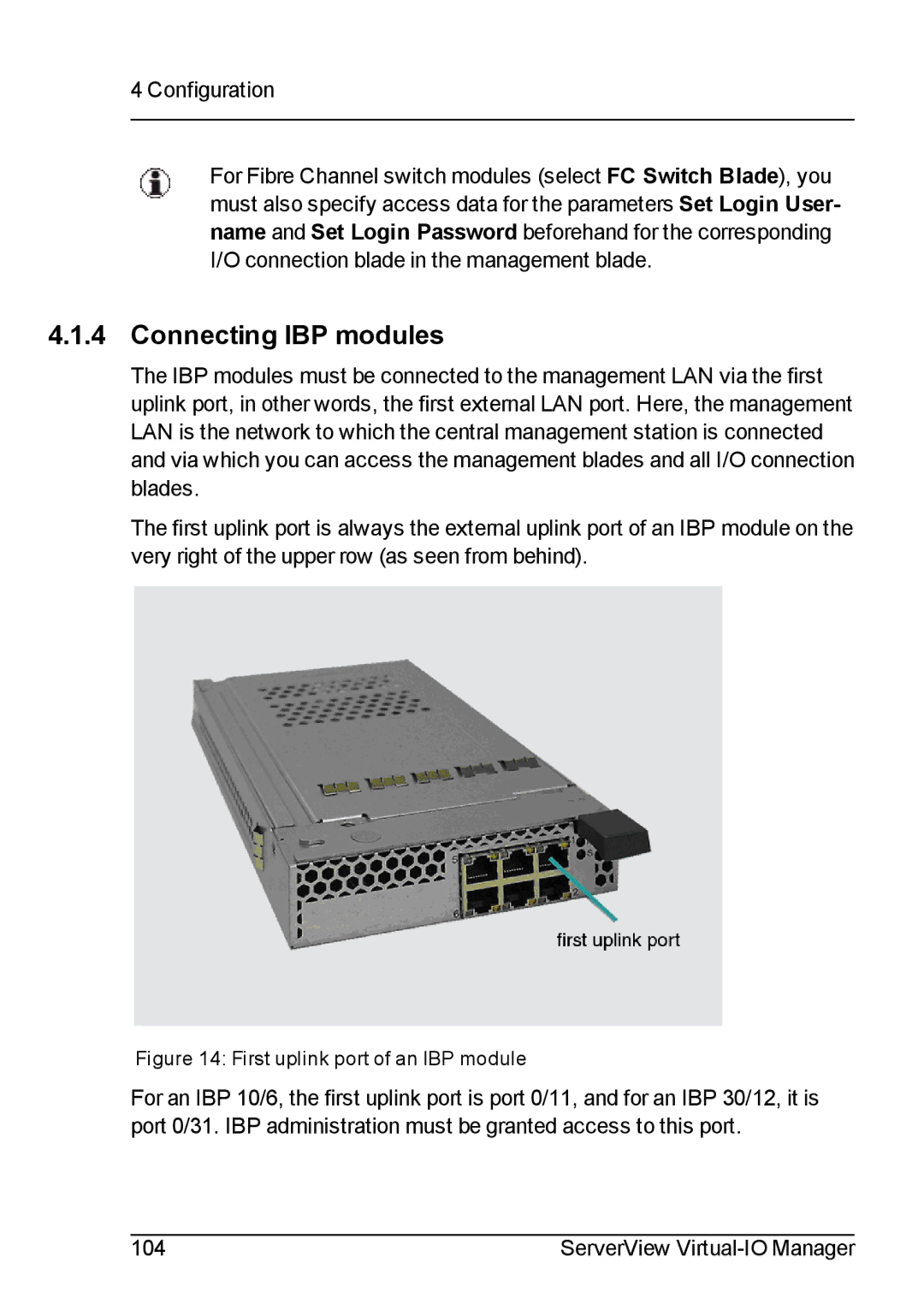
The first uplink port is always the external uplink port of an IBP module on the very right of the upper row (as seen from behind).
Figure 14: First uplink port of an IBP module
For an IBP 10/6, the first uplink port is port 0/11, and for an IBP 30/12, it is port 0/31. IBP administration must be granted access to this port.
104 | ServerView |