. . . . . . . . . . . . . . . . . . . . . . . . . . . . .
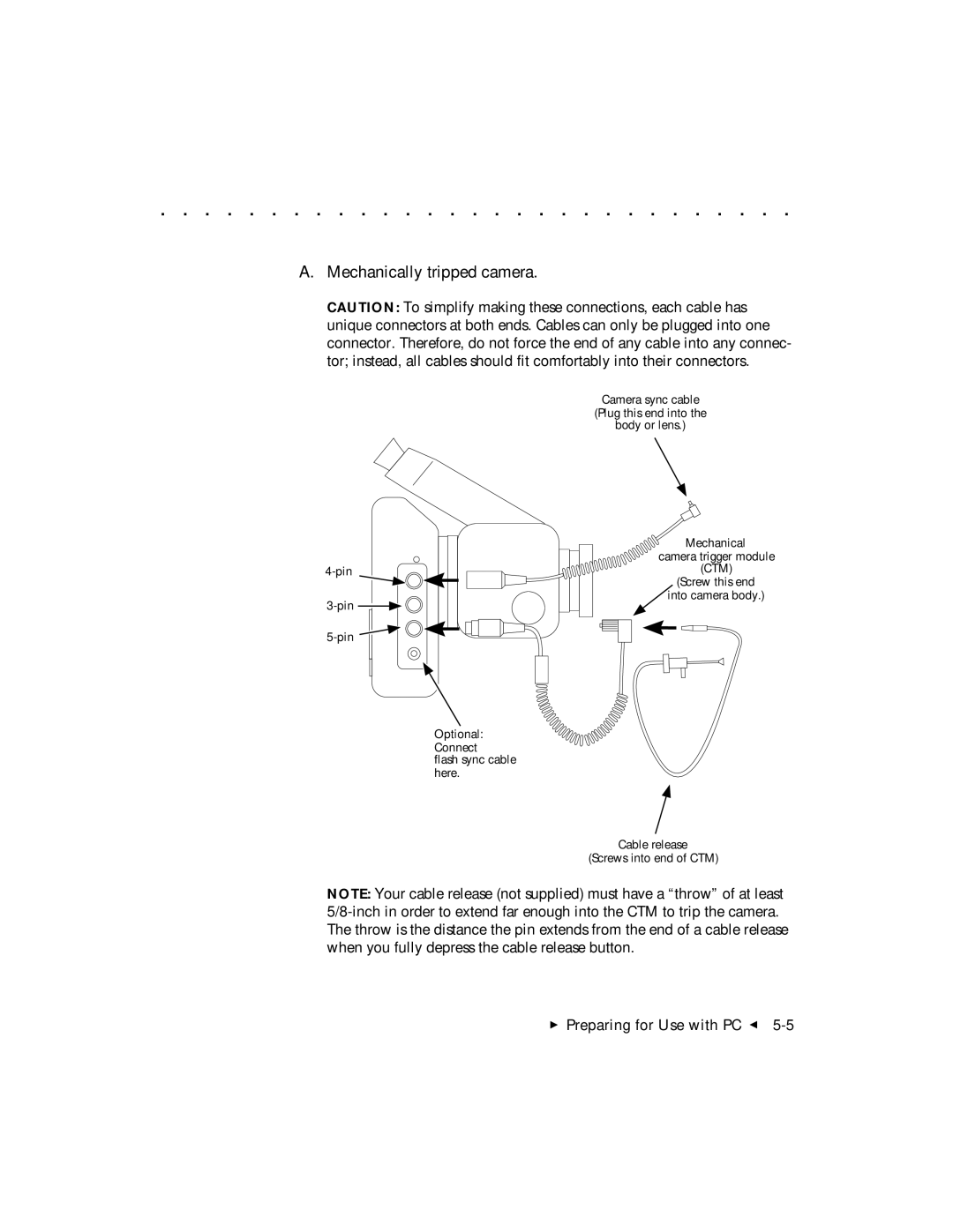
A.Mechanically tripped camera.
CAUTION: To simplify making these connections, each cable has unique connectors at both ends. Cables can only be plugged into one connector. Therefore, do not force the end of any cable into any connec- tor; instead, all cables should fit comfortably into their connectors.
Camera sync cable
(Plug this end into the
body or lens.)
Optional:
Connect
flash sync cable here.
Mechanical
camera trigger module (CTM)
(Screw this end ![]() into camera body.)
into camera body.)
Cable release
(Screws into end of CTM)
NOTE: Your cable release (not supplied) must have a “throw” of at least
Preparing for Use with PC G
