. . . . . . . . . . . . . . . . . . . . . . . . . . . . .
7.Make the appropriate cable connections; follow step A for mechani- cally tripped cameras, and step B for electrically tripped cameras.
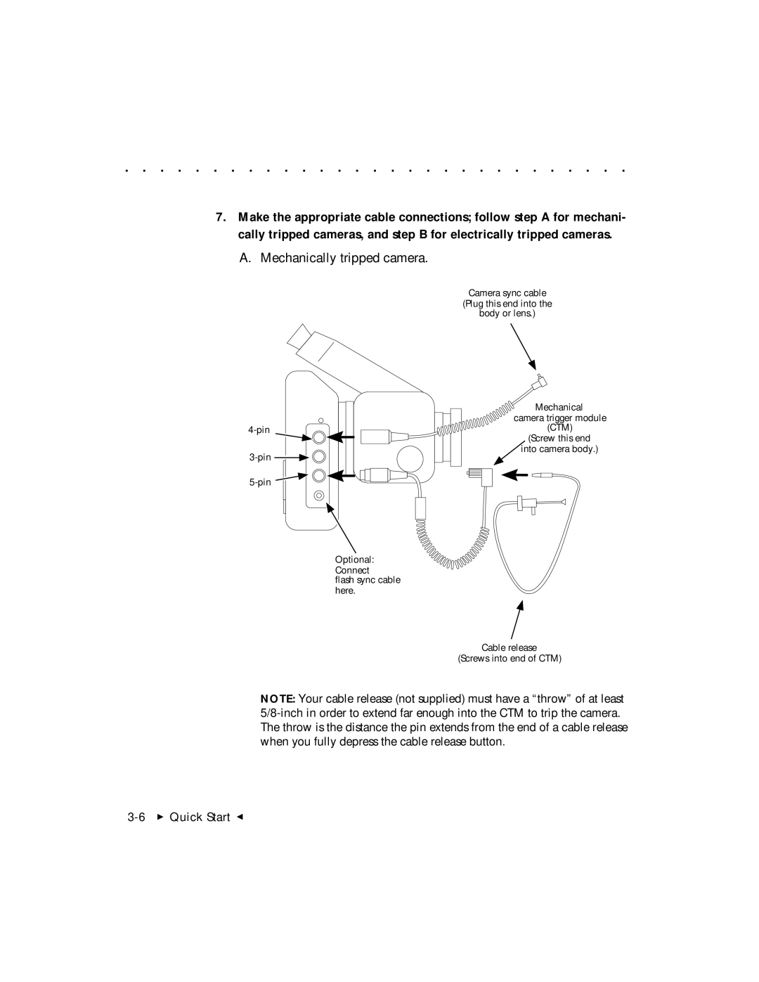
A. Mechanically tripped camera.
Camera sync cable
(Plug this end into the
body or lens.)
Optional:
Connect
flash sync cable here.
Mechanical
camera trigger module (CTM)
(Screw this end ![]() into camera body.)
into camera body.)
Cable release
(Screws into end of CTM)
NOTE: Your cable release (not supplied) must have a “throw” of at least