M P a X U s e r G u i d e
Contents
Compax 25XXS unit characteristics
Compax 45XXS/85XXS unit characteristics
Compax 1000SL Unit characteristics
Technical data
Contents
173
Optimization functions 125
Interfaces 138
Process interfaces 179
226
Appendix 207
238
General dangers
Compax 0260M
Key to unit designation Hauser type plate
Please check the software version of your unit
Safety instructions
Special safety instructions
General dangers
Safe working practices
Conditions of warranty
Conditions of warranty
Switch-on status
Configuration when supplied
Commissioning
COMPAX-M / -S LED
Motor is powered Compax display shows RUN Flow chart
Configuring
Commissioning
Equipment replacement
Previous software ≥
Transferring system parameters
Previous software ≤
Equipment replacement
NMD10 / Compax 45XXS / Compax 85XXS
Compax 35XXM
Compax 25XXS
Overview
Start-up manual
Components required
Common function characteristics
Overview
Overview of unit technology
Compax P1XXM COMPAX-M
Dimensions DxHxW 146*180*85 mm Design
Design Power KVA
Dimensions DxHxW 275*350*125 mm Design Power KVA
KVA
COMPAX-M unit features
COMPAX-M unit features
Connector and terminal assignment
Connector and terminal assignment
Short circuit connectors
COMPAX-M system network, NMD10 / NMD20 mains module
Wiring up mains
Power / control
Voltage Power supply Control voltage
Screened Connection Upper unit side
Compax P1XXM, Compax 05XXM, Compax 15XXM
COMPAX-M dimensions/installation
Compax 02XXM, NMD10, NMD20
Connector assignment COMPAX-M
Connector assignment COMPAX-M
Mains module NMD10/NMD20
Dimensions / installation
Overview NMD
NMD connector assignment
Technical data / power features NMD
Mains module NMD10/NMD20
CE conformity
NMD10
NMD20
If a phase malfunctions, no displays appear
Technical data / power features NMD
LED red LED green Possible errors Error Ready
Ready contact and green LED are coupled
Compax 35XXS unit features
Plug and connection assignment Compax 35XXM
Compax 35XXS unit features
Installation and dimensions of Compax 35XXM
Specific technical data
Regeneration mode
Wiring Compax 35XXM
PE connection must be a version of at least 10mm2
Compax 35XXM connector assignment
Assignment of X12 does not apply for the S3 option
Compax 25XXS unit characteristics
Compax 25XXS connector and connection assignment
LED / color Meaning, when switched on
Meaning of the LEDs on the front plate
Compax 25XXS unit characteristics
Wiring up motor
Compax 25XXS connector and connection assignment
On unit side
Compax 25XXS-specific technical data
Connecting ballast resistance to COMPAX-S
Compax 25XXS 1000 ∝ F / 27 Ws
Compax 25XXS ≤ 1.0 kW Unlimited With R ext ≥ 56 Ω ≤ 2.5 kW
Compax 25XXS dimensions / installation
Compax 25XXS dimensions / installation
Design in series
Flat design
Connector assignment Compax 25XXS
O1...O8
Compax 45XXS/85XXS unit characteristics
Compax 45XXS/85XXS unit characteristics
Plug and connection assignment Compax 45XXS/85XXS
Plug and connection assignment Compax 45XXS/85XXS
Compax 45XXS/85XXS installation / dimensions
Meaning of the LEDs on the front plate
Wiring up motor Control voltage Enable
Compax 45XXS/85XXS-specific wiring
Compax 45XXS/85XXS-specific wiring
Enable internal ballast resistance X2/5 X2/6
Enable bridges
Maximum braking power of the internal ballast resistance
Compax 45XXS/85XXS connector and pin assignment
Assignment/ cable
Compax 1000SL Unit characteristics
Connector and terminal assignment for Compax 1000SL
PE terminal
LED display
Compax 1000SL Unit characteristics
Unit wiring
Connector and terminal assignment for Compax 1000SL
Compax 10XXSL 660 ∝ F / 17 Ws
Mating connectors X1, X2, X3
Connector assignment Compax 1000SL overview
Bridges for test operation
Mounting and dimensions Compax 1000SL
Mounting and dimensions Compax 1000SL
Readiness, safety chain Emergency stop
Safety chain / emergency stop functions
Emergency stop and ready on connector
Emergency stop input direct to COMPAX-M
Emergency stop input on COMPAX-M
Ready contact max .5A
60V, 30W
Connections to the motor
Resolver / SinCos
Cable assignment in the terminal boxes
Resolver / SinCos
Connections to the motor
Length codes for preformed cables
Length m
Code
Procedure
MOK42 max ,8A
Packaging of device
Material
MOK21 max ,9A
MOK21
SinCos cable for HJ and HDY motors
Version in high-flex GBK17 same layout
Connections to the motor Additional brake control
External contact connection
Interfaces
Digital inputs and outputs excluding Compax 1000SL
Assignment of X8 Input/Output
Assignment of X10 Input/Output
Interfaces Digital inputs and outputs for Compax 1000SL
GND
Start
24VDC
Technical data / Connections of inputs and outputs
Compax 1000SL
Interfaces Initiators and D/A monitor
Connection plan for the initiators with initiator connector
Connection assignment on
Service D/A monitor / override
Service D/A monitor
Service D/A monitor / override
Wiring of override with screened cables only
Interfaces
Monitor
Standard
Measuring
7 D/A monitor option D1
Meaning and range of values of P71 P74
Wiring diagram SSK1/...COMPAX PC/terminal
8 RS232 interface
Absolute value sensor option A1 Interfaces
Cable plan GBK1/.. Compax absolute value sensor
Encoder interfaces / analogue rpm specification for Compax
10 X13 Encoder interfaces
Area of application of process interfaces
Assignment on
Process interfaces Configuration options
Encoder interface Step direction input for Compax 1000SL
Configuring
Process
Interfaces
Applications with Compax 1000SL and encoder
Interfaces Heda interface option A1/A4
Bus connection
Cable plan
SSK14
Technical data
Power characteristics
Bus connection optional
Housing
Permissible 3-phase mains
Operation
Standard delivery
Operating Instructions
Operating Instructions
PLC data interface
RS232 / RS485 Bus-Systems
Program memory / parameter memory
Setting Parameters
Explanations for the block structure
Functions
System controller
Password protection
Interfaces for signals
Password Protection Activate password
Deactivate
Configuration
Configuration
Meaning of the bus parameters Acknowledging error messages
Front plate operation not available with Compax 1000SL
Configuration when supplied
Configuration process
Power on with motor switched off
Switching off the drive Modifying parameters
Power on for drive
Safety instructions for initial start-up
Risks from incorrect wiring
Configuration parameters
Operating mode
Normal mode Continuous mode Speed controller
Unit for travel data
Ramps
Motor type
Linear
Drive type
Spindle drive
Smooth Quadratic
Transfer of P94
General drive
Reference system
P215 direction of rotation
P213=0 P213=1
Specifying software end limits
Absolute value function with standard resolver
Activated with
P206=2
Absolute value function with standard resolver
Machine zero mode
Real zero
Machine zero
P213 Standard machine Zero mode for linear Movements
Machine zero equals external initiator & resolver zero
Additional machine zero modes
P212 =1 Find machine zero Application
Machine zero initiator MZ-INI is
Low active
Resolver zero pulse is a fixed
Position of the rotor position
Machine zero equals external zero pulse
Conditions for this operating mode
P213=0 P29=0 P29=90 General rotatory
P212=4 only permitted for Compax XX00 and Compax
Find machine zero Application
P212 =5 Find machine zero Application
Machine zero equals resolver zero
P212 =7 Find machine zero Application
Wiring up
Function
Condition
P212 =8 Find machine zero Application
Operating Instructions
Limit switch operation
COMPAX-M / -S
Configuration via PC using ServoManager
Configuration via PC using ServoManager
Installing ServoManager
Configuring Compax
Other parameters are derived from the type plate data
Nominal motor speed for the Hbmr motors
EMC
Min-1
Holding brake For motors with holding brake
Parameter for saturation characteristic curve
Drive type
Safety instructions for the first start-up
Individual configuration of synchronous motors
Positioning and control functions
Positioning and control functions
Start program
Absolute positioning Posa
Relative positioning Posr
Absolute positioning Posa
Posa value
Process velocity Speed
Acceleration and braking time Accel
Setting/resetting an output Output
Setting multiple digital outputs Output O12=1010
Switch off drive unit. Output O0
O12=1010
Password Goto
External velocity specification. Speed Sync
Password Goto
External speed set via option E7
Mark-related positioning Posr
Preparatory instructions
Changes in speed within a positioning process Posr Speed
Preparatory instructions
Syntax Example
Compatibility
Posr x Speed y Accel z
Speed step profile extended by ramp time
Changes in speed within a positioning process Posr Speed
Diagram of specified example for Posr Output
Diagram of example using Posa -1000 as positioning
Comparators during positioning Posr Output
Comparators during positioning Posr Output
Cam controller with compensation for switching delays
Cam controller with compensation for switching delays
Function of the cam controller
Outputs of the cam controller
Explanation regarding cam controller
Problem point
105
Example 2 Positioning with subsequent cam operation Compax
Explanation
Rogrammable waiting time Wait
Program jump Goto
Sub-program jump Gosub
Instruction to end a sub-program. Return
Start a program loop Repeat
Branching if I7=1
If I7=1
Binary if query of inputs if I12=101-1
Specific processing of data record groups. Wait Start
Comparative operations
Jump with data record selection Goto EXT
Error handling if Error Gosub
Function Priority Error program
If Error Gosub
Sub-program jump with data record selection Gosub EXT
Error program with
Stop / Break handling if Stop Gosub
Wait Start
Stop / Break handling if Stop Gosub
Stop program
N001 if Stop Gosub
N241 Wait Start
N243 Return
Arithmetic
Parameter assignments
Curve memory
Example
Arithmetic and variables
Status values Variables
Or absolute
Division y = x1 Example
115
Read status and assign variables Initializing variables
Position monitoring P93=1, 2
Functional description
OM2
OM3
OM2 O5 = 1 nominal value reached and lag error P14
OM3 O5 = 1 nominal value reached
Idle display
Idle display
Bit counting begins with 119
Speed monitoring in speed control mode P93=4
OM1 O5 toggles when speed is reached
Can be adjusted using P227 bit 429 =0 default setting
OM3 O5 =
Nominal value
Reached
PLC sequential step tracking
PLC sequential step tracking
Implementation
Final stage blocked by Final stage is enabled via
Engaging and disengaging the motor brake
Via
Range of values
Output of variable voltage
Service D/A monitor channels
Option D/A monitor channels
User-defined settings
Optimization functions
Optimizing the movement cycle
Optimizing with the ServoManager
User-defined settings with variant P59=
Output of variable voltage Optimization process
Sensor
Increase control dynamic
P59 Structure switch measuring P23 stiffness of drive
Optimization parameters
Structure
Variants
P56 D section rpm controller
P24 damping of drive
Increase damping Reduce damping
Advance control of speed, acceleration and power
Optimization functions
Advance control measures
Without advance control measures
P26 Advance acceleration control P70 Advance power control
P25 Advance
Speed control
Advance speed control
Control processes for optimization
Accel
Function Settings Using the speed monitor
Speed monitor
Speed monitor
Speed determination standard
Optimization display
Optimization display
P233/P23430 Meaning
Square of peak motor current
You will find a complete status list on Page207
Reference value 80 000A2
Use the effective value
Access to additional parameters via S13 and S14
P233/P234 Meaning
Configuring the external position adjustment
External position localization with position adjustment
Only available in Compax
Slip filter for external position localization
Limit values
P214
Drive type Measuring unit Determining
Digital inputs and outputs
Assignment of standard unit
Digital inputs and outputs
Input Assignment
Digital inputs and outputs Output Assignment
Allocation of logic inputs for input pins
Digital inputs and outputs for Compax 1000SL
P156 bit
P157 bit
Following assignment must be configured Input X19 pin
Digital inputs and outputs Example
Operating Instructions
Free assignment of inputs and outputs
Free assignment
Inputs
Free assignment of outputs
Output Function Valency
Compax virtual inputs
Heda
Remarks regarding the structural diagram
Interrogation of inputs in the Compax program if
1.4 I/O assignment of variants
Hand+/Hand
Function of inputs
Exception Start
Approach RZ
Find MZ
Input Shift
Activate position adjustment
Break
P211 blocking and modifying teach in functions
Quit Start Stop
Synchronous Stop using
Diagram
Fast start
Synchronous Stop
Additional assignment of P219
Function of outputs
No fault
No warning
Data record memory mode
Diagrams
Caption
Direct command
Specification
Finding machine zero in normal mode Approaching real zero
Before the 1st machine zero travel, O3=0
Input/output Meaning
BCD coded
Acceleration time
Syntax of individual commands
157
Operating Instructions
Commands
Procedure for transmitting a sign
Signal procedure using the example of a status query
Function codes
3 RS232 interface
Interface description
RS232 interface Function Activation using P20 Valid From
$=com19600,N,8,1
Interface functions Direct command entry
Commands permitted for the various modes of operation
Positioning commands
Influencing the active positioning process
Read the status values
Read and write program sets and parameters
Negative command acknowledge- ment
Transmitting control instructions
P211 blocking and modifying the teach in functions
Quit
Commands available
All operating modes
Statuses
Output O0
P20 switching on binary data transfer
Binary data transfer using RS232
Meanings of the binary command codes
RS232 interface Valency *1
Examples of the number format of xx xx xx xx xx Number
MSB LSB
360 450,5
Process coupling using Heda Option A1 / A4
Transmittable parameters Master output quantity
Fast start
Slave input quantities
P98 is identical in all units
Permissible combinations and required parameter settings
Application examples 1st unit Master Slave
Error handling
Error messages
Synchronizing
Process values
172
System concept
System concept
Accessories and options
174
Power module NMD
Options
Unit Nominal Peak current Power kVA
Motors
EMD motors Linear motor
Current Aeff Aeff 5s With mains supply 230V AC
Hauser linear actuators
Hauser linear actuators
Initiator set
177
1 RS232
Data interfaces
Bus systems
Process interfaces
Process interfaces
Encoder interface
Meaning Unit
Individual connections
Encoder module and accessories
Applications with encoder
Compax Compax
Compax not
Requirements per Compax EAM 4/01
BUS 1/01
Following are required
Encoder bus mixed
Encoder module
High resolution SinCos sensor system S1/S2
Technical data
Enable absolute value sensor input
Process interfaces Absolute value sensor A1
Option S3 for linear motors
S2 option
SinCos multi-turn with programmable transmission factor
See 184
Process interfaces Heda interface
6 D/A monitor D1 option not available with Compax 1000SL
Configuration Accuracy Connection assignment
Connector Pin X13 or
Signal Circuit proposal EAM4/01 Input
I16 = 1 external nominal value is valid
Accessories
BDF1/02 for front plate installation
BDF1/03 with housing
External control panel not available for Compax 1000SL
Wiring plan
Terminal module for Compax 1000SL EAM
Terminal assignment
SSK6
3 EAM5/01 DC feed for COMPAX-M
EAM5/01 DC feed for COMPAX-M
Input voltage range 100V DC 650V DC
Design of EAM5/01
Delivery scope
EMC measures
Power filter
NMD10 / Compax 45XXS / 85XXS
Motor output throttle
Length of connection between power filter
Compax 25XXS Compax 10XXSL
Dimension diagram BRM4, BRM6 and BRM7
BRM5/01 is fitted with a 0.3m connecting cable
External ballast resistors
Compax 25XXS with external ballast resistance of 56Ω
Diagrams Brake pulse power cooling period
Authorised braking impulse power with NMD20
Maximum permitted length
Is 2m
Authorised braking impulse power for NMD20 with BRM4/02
195
Authorised braking impulse power for NMD20 with BRM4/01
196
Compax 8500S
Authorised braking impulse power for Compax 4500S
197
198
199
ServoManager
Hand-held terminal
ServoManager
200
Special Compax XX70 commands
Hand-held terminal Functions
Keys Function
Special functions
Hand-held terminal Menu
Status Level
View Edit, delete program
Hand-held terminal
View, edit and reset parameter
View, set configuration
VC is generated when you exit the menu
Exits the menu without VC
Set configuration
205
Appendix Compax components
206
Status values of the standard unit Compax
Status values of the standard unit Compax XX00
Actual values
Diagnosis values
Appendix
Unit designations
Special Compax XX00 status values
Meaning of status bits
Output of status bits via the front plate
Explanation of error history S18
S16, S17
Selection of status value using P182 Measuring parameter
Additional Compax measuring quantites
Status monitor S15
Scaled longitudinal voltage For amplification 1 use 10V =
Additional Compax measuring quantites
211
VP parameter46can be modified On Line
Compax parameter
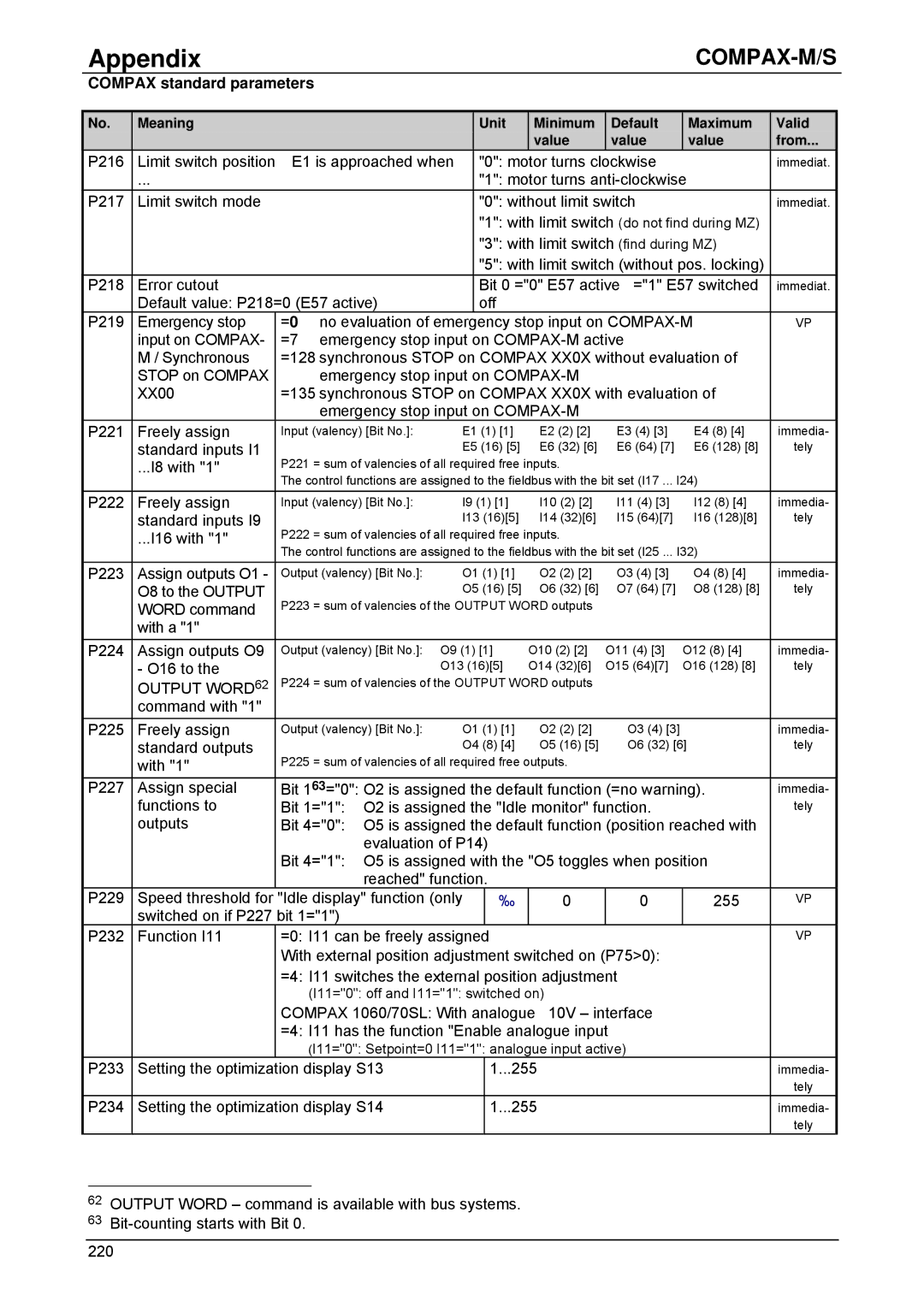
Compax standard parameters
Only permitted with P18 when bit 1=1
Compax parameter
Remark
List of parameters, sorted by number
P20 setting
Compax standard parameters
Rack
Drive Type Spindle drive P80=2
General drive drive type P80=16
EMC
P112 Slip frequency MHz 100 P113 Maximum speed Min-1 9000
P115 Angular speed 100 200
P144 Settting encoder channel
X19
Source for
Bit 0 Input
Default value P184=0
Enable final stage with Output O0=0 without
P212 Machine zero mode
Settings 3 and 4 with Compax XX00
Output Word
P243 Heda operation
Mode
P245 Assign outputs O1
O8 to the Heda
Monitoring and limitation characteristics
Structural diagram
Dynamic monitoring
Static monitoring
Error handling and error messages
Error handling and error messages
With Compax 70 Curve number not present 223
224
Too hard E40
Response to lag error error E10 Position controller
Response to E15
Quit is not required
Speed control mode, control is referenced to speed
Application examples
Wiring up the digital inputs and outputs
External data record selection
Application
Assignments
Configuration
Programming
Names of inputs and outputs
List of programs
Mark-referenced positioning
Mark-referenced positioning
Sets the acceleration and braking ramp
N003 Output O7=0 Shears = block
Mark reference = block
Message = mark found
Speed step profiling / comparator switching points
Speed step profiling / comparator switching points
Names of the inputs and outputs
Speed Sync
Design and wiring up of the digital inputs and outputs
Speed control mode
Speed control mode
N019 if I10=0 Goto removing Operating mode query
Light barrier
Interlock # closed # open
Sets the accelerating and braking ramps to 10s
Assignments Function
Fast start
Fast start
Using speed control mode
Position controller mode
Changing error response
Implementing a torque controller
COMPAX-25XXS
Index
COMPAX-M / NMD
If Error Gosub
Installation / dimensions
Installation Dimensions
Installation arrangement COMPAX-M
Limit switch monitoring Without locking
Power on with motor
Power with linear motor
Process interfaces Configuration options
Safety chain Emergency stop
Compax 25XXS Compax 45/85S COMPAX-M
Compax 25XXS Compax 45/85S