U | V | W | R2A | R2C | ◆ | LineCont.eps |
KM2 |
| KM2 | TS |
| 120 VAC |
|
|
|
|
| |||
U1 | V1 | W1 | TS = Transient suppressor |
| ||
|
|
|
| |||
◆ See Specifications section for
Mcontactor ratings.
3 Phase
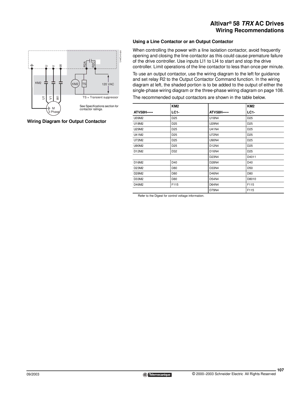
Wiring Diagram for Output Contactor
09/2003
Altivar® 58 TRX AC Drives
Wiring Recommendations
Using a Line Contactor or an Output Contactor
When controlling the power with a line isolation contactor, avoid frequently opening and closing the line contactor as this could cause premature failure of the drive controller. Use inputs LI1 to LI4 to start and stop the drive controller. Limit operations of the line contactor to less than once per minute.
To use an output contactor, use the wiring diagram to the left for guidance and set relay R2 to the Output Contactor Command function. In the wiring diagram at left, the shaded portion is to be added to the output of either the
The recommended output contactors are shown in the table below.
| KM2 |
| KM2 |
ATV58H••••• | LC1- | ATV58H••••• | LC1- |
|
|
|
|
U09M2 | D25◆ | U18N4 | D25◆ |
U18M2 | D25◆ | U29N4 | D25◆ |
U29M2 | D25◆ | U41N4 | D25◆ |
U41M2 | D25◆ | U72N4 | D25◆ |
U72M2 | D25◆ | U90N4 | D25◆ |
U90M2 | D25◆ | D12N4 | D25◆ |
D12M2 | D32◆ | D16N4 | D25◆ |
|
| D23N4 | D4011◆ |
D16M2 | D40◆ | D28N4 | D40◆ |
D23M2 | D80◆ | D33N4 | D50◆ |
D28M2 | D80◆ | D46N4 | D80◆ |
D33M2 | D80◆ | D54N4 | D8010◆ |
D46M2 | F115◆ | D64N4 | F115◆ |
|
| D79N4 | F115◆ |
◆Refer to the Digest for control voltage information.
107
©