|
|
|
|
|
|
|
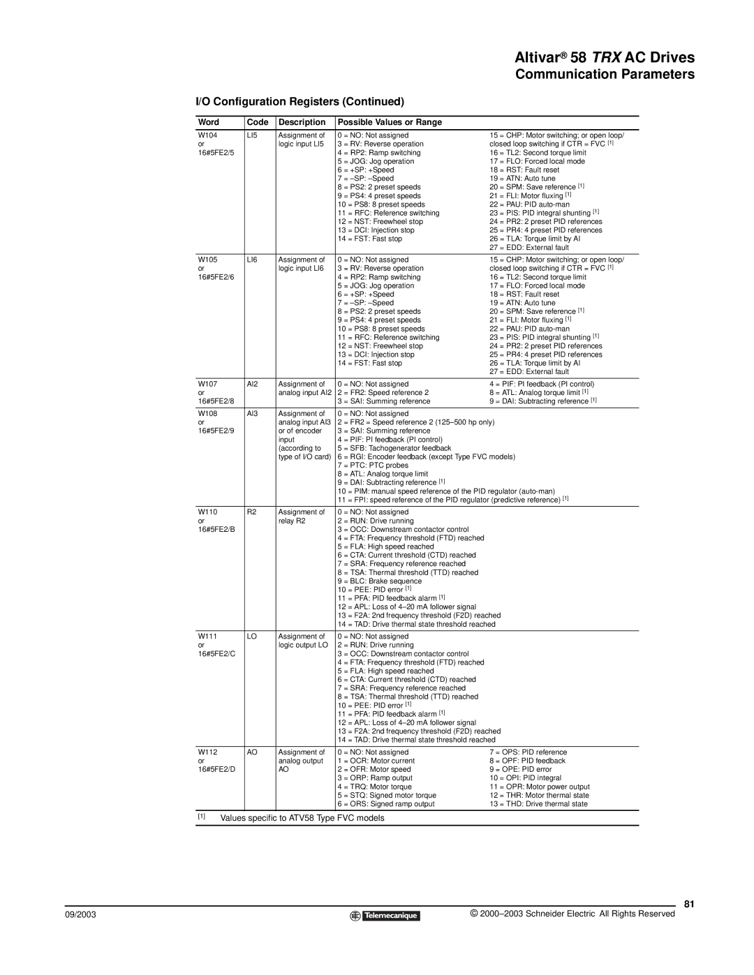
| Altivar® 58 TRX AC Drives | |
|
|
|
|
|
|
|
| Communication Parameters | |
I/O Configuration Registers (Continued) |
|
|
| ||||||
|
|
|
|
|
|
|
| ||
Word |
| Code | Description | Possible Values or Range |
|
|
| ||
|
|
|
|
|
|
|
| ||
W104 |
| LI5 | Assignment of | 0 = NO: Not assigned | 15 | = CHP: Motor switching; or open loop/ | |||
or |
|
| logic input LI5 | 3 = RV: Reverse operation | closed loop switching if CTR = FVC [1] | ||||
16#5FE2/5 |
|
| 4 = RP2: Ramp switching | 16 | = TL2: Second torque limit | ||||
|
|
|
| 5 | = JOG: Jog operation | 17 | = FLO: Forced local mode | ||
|
|
|
| 6 | = +SP: +Speed | 18 | = RST: Fault reset | ||
|
|
|
| 7 | = | 19 | = ATN: Auto tune | ||
|
|
|
| 8 | = PS2: 2 preset speeds | 20 | = SPM: Save reference [1] | ||
|
|
|
| 9 | = PS4: 4 preset speeds | 21 | = FLI: Motor fluxing [1] | ||
|
|
|
| 10 | = PS8: 8 preset speeds | 22 | = PAU: PID | ||
|
|
|
| 11 | = RFC: Reference switching | 23 | = PIS: PID integral shunting [1] | ||
|
|
|
| 12 | = NST: Freewheel stop | 24 | = PR2: 2 preset PID references | ||
|
|
|
| 13 | = DCI: Injection stop | 25 | = PR4: 4 preset PID references | ||
|
|
|
| 14 | = FST: Fast stop | 26 | = TLA: Torque limit by AI | ||
|
|
|
|
|
|
| 27 | = EDD: External fault | |
|
|
|
|
|
|
|
| ||
W105 |
| LI6 | Assignment of | 0 = NO: Not assigned | 15 | = CHP: Motor switching; or open loop/ | |||
or |
|
| logic input LI6 | 3 = RV: Reverse operation | closed loop switching if CTR = FVC [1] | ||||
16#5FE2/6 |
|
| 4 = RP2: Ramp switching | 16 | = TL2: Second torque limit | ||||
|
|
|
| 5 | = JOG: Jog operation | 17 | = FLO: Forced local mode | ||
|
|
|
| 6 | = +SP: +Speed | 18 | = RST: Fault reset | ||
|
|
|
| 7 | = | 19 | = ATN: Auto tune | ||
|
|
|
| 8 | = PS2: 2 preset speeds | 20 | = SPM: Save reference [1] | ||
|
|
|
| 9 | = PS4: 4 preset speeds | 21 | = FLI: Motor fluxing [1] | ||
|
|
|
| 10 | = PS8: 8 preset speeds | 22 | = PAU: PID | ||
|
|
|
| 11 | = RFC: Reference switching | 23 | = PIS: PID integral shunting [1] | ||
|
|
|
| 12 | = NST: Freewheel stop | 24 | = PR2: 2 preset PID references | ||
|
|
|
| 13 | = DCI: Injection stop | 25 | = PR4: 4 preset PID references | ||
|
|
|
| 14 | = FST: Fast stop | 26 | = TLA: Torque limit by AI | ||
|
|
|
|
|
|
| 27 | = EDD: External fault | |
|
|
|
|
|
|
| |||
W107 |
| AI2 | Assignment of | 0 = NO: Not assigned | 4 = PIF: PI feedback (PI control) | ||||
or |
|
| analog input AI2 | 2 = FR2: Speed reference 2 | 8 = ATL: Analog torque limit [1] | ||||
16#5FE2/8 |
|
| 3 = SAI: Summing reference | 9 = DAI: Subtracting reference [1] | |||||
W108 |
| AI3 | Assignment of | 0 = NO: Not assigned |
|
|
| ||
or |
|
| analog input AI3 | 2 = FR2 = Speed reference 2 |
|
| |||
16#5FE2/9 |
| or of encoder | 3 = SAI: Summing reference |
|
|
| |||
|
|
| input | 4 = PIF: PI feedback (PI control) |
|
|
| ||
|
|
| (according to | 5 = SFB: Tachogenerator feedback |
|
|
| ||
|
|
| type of I/O card) | 6 = RGI: Encoder feedback (except Type FVC models) | |||||
|
|
|
| 7 | = PTC: PTC probes |
|
|
| |
|
|
|
| 8 | = ATL: Analog torque limit |
|
|
| |
|
|
|
| 9 | = DAI: Subtracting reference [1] |
|
|
| |
|
|
|
| 10 | = PIM: manual speed reference of the PID regulator | ||||
|
|
|
| 11 | = FPI: speed reference of the PID regulator (predictive reference) [1] | ||||
W110 |
| R2 | Assignment of | 0 = NO: Not assigned |
|
|
| ||
or |
|
| relay R2 | 2 = RUN: Drive running |
|
|
| ||
16#5FE2/B |
|
| 3 = OCC: Downstream contactor control |
|
|
| |||
|
|
|
| 4 | = FTA: Frequency threshold (FTD) reached |
|
|
| |
|
|
|
| 5 | = FLA: High speed reached |
|
|
| |
|
|
|
| 6 | = CTA: Current threshold (CTD) reached |
|
|
| |
|
|
|
| 7 | = SRA: Frequency reference reached |
|
|
| |
|
|
|
| 8 | = TSA: Thermal threshold (TTD) reached |
|
|
| |
|
|
|
| 9 | = BLC: Brake sequence |
|
|
| |
|
|
|
| 10 | = PEE: PID error [1] |
|
|
| |
|
|
|
| 11 | = PFA: PID feedback alarm [1] |
|
|
| |
|
|
|
| 12 | = APL: Loss of |
|
|
| |
|
|
|
| 13 | = F2A: 2nd frequency threshold (F2D) reached | ||||
|
|
|
| 14 | = TAD: Drive thermal state threshold reached |
|
| ||
|
|
|
|
|
|
|
| ||
W111 |
| LO | Assignment of | 0 = NO: Not assigned |
|
|
| ||
or |
|
| logic output LO | 2 = RUN: Drive running |
|
|
| ||
16#5FE2/C |
|
| 3 = OCC: Downstream contactor control |
|
|
| |||
|
|
|
| 4 | = FTA: Frequency threshold (FTD) reached |
|
|
| |
|
|
|
| 5 | = FLA: High speed reached |
|
|
| |
|
|
|
| 6 | = CTA: Current threshold (CTD) reached |
|
|
| |
|
|
|
| 7 | = SRA: Frequency reference reached |
|
|
| |
|
|
|
| 8 | = TSA: Thermal threshold (TTD) reached |
|
|
| |
|
|
|
| 10 | = PEE: PID error [1] |
|
|
| |
|
|
|
| 11 | = PFA: PID feedback alarm [1] |
|
|
| |
|
|
|
| 12 | = APL: Loss of |
|
|
| |
|
|
|
| 13 | = F2A: 2nd frequency threshold (F2D) reached | ||||
|
|
|
| 14 | = TAD: Drive thermal state threshold reached |
|
| ||
|
|
|
|
|
|
| |||
W112 |
| AO | Assignment of | 0 = NO: Not assigned | 7 = OPS: PID reference | ||||
or |
|
| analog output | 1 = OCR: Motor current | 8 = OPF: PID feedback | ||||
16#5FE2/D |
| AO | 2 = OFR: Motor speed | 9 = OPE: PID error | |||||
|
|
|
| 3 | = ORP: Ramp output | 10 | = OPI: PID integral | ||
|
|
|
| 4 | = TRQ: Motor torque | 11 | = OPR: Motor power output | ||
|
|
|
| 5 | = STQ: Signed motor torque | 12 | = THR: Motor thermal state | ||
|
|
|
| 6 | = ORS: Signed ramp output | 13 | = THD: Drive thermal state | ||
|
|
|
|
|
|
|
| ||
[1] | Values specific to ATV58 Type FVC models |
|
|
| |||||
|
|
|
|
|
|
|
|
|
|
81
09/2003 |
| © |
| ||
|
|
|