Altivar® 58 TRX AC Drives
Adjustment Parameters
High | HiLoSpd.eps |
Speed | |
| |
Low |
|
Speed |
|
0 V | 10 V |
0 mA | 20 mA |
x mA | y mA |
20 mA | 4 mA |
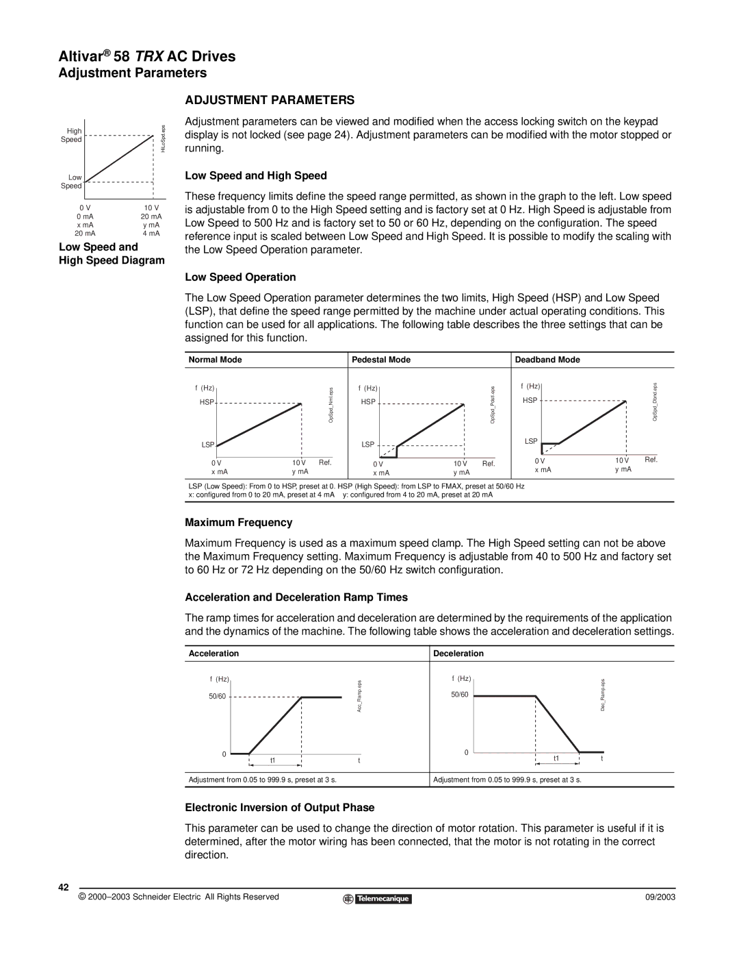
Low Speed and High Speed Diagram
ADJUSTMENT PARAMETERS
Adjustment parameters can be viewed and modified when the access locking switch on the keypad display is not locked (see page 24). Adjustment parameters can be modified with the motor stopped or running.
Low Speed and High Speed
These frequency limits define the speed range permitted, as shown in the graph to the left. Low speed is adjustable from 0 to the High Speed setting and is factory set at 0 Hz. High Speed is adjustable from Low Speed to 500 Hz and is factory set to 50 or 60 Hz, depending on the configuration. The speed reference input is scaled between Low Speed and High Speed. It is possible to modify the scaling with the Low Speed Operation parameter.
Low Speed Operation
The Low Speed Operation parameter determines the two limits, High Speed (HSP) and Low Speed (LSP), that define the speed range permitted by the machine under actual operating conditions. This function can be used for all applications. The following table describes the three settings that can be assigned for this function.
Normal Mode
f(Hz)
HSP
LSP
0V x mA
| OpSpd Nml.eps |
10 V | Ref. |
ymA
Pedestal Mode
f (Hz) |
| Pdstl.eps |
HSP |
| |
|
| OpSpd_ |
LSP |
|
|
0 V | 10 V | Ref. |
x mA | y mA |
|
Deadband Mode
HSP | Dbnd.eps |
f (Hz) |
|
| OpSpd_ |
LSP |
|
0 V | 10 V Ref. |
x mA | y mA |
LSP (Low Speed): From 0 to HSP, preset at 0. HSP (High Speed): from LSP to FMAX, preset at 50/60 Hz
x: configured from 0 to 20 mA, preset at 4 mA y: configured from 4 to 20 mA, preset at 20 mA
Maximum Frequency
Maximum Frequency is used as a maximum speed clamp. The High Speed setting can not be above the Maximum Frequency setting. Maximum Frequency is adjustable from 40 to 500 Hz and factory set to 60 Hz or 72 Hz depending on the 50/60 Hz switch configuration.
Acceleration and Deceleration Ramp Times
The ramp times for acceleration and deceleration are determined by the requirements of the application and the dynamics of the machine. The following table shows the acceleration and deceleration settings.
Acceleration
f (Hz)
50/60 ![]()
Acc_Ramp.eps
Deceleration
f(Hz)
50/60
Dec_Ramp.eps
0
t1 | t |
0
t1t
Adjustment from 0.05 to 999.9 s, preset at 3 s.
Adjustment from 0.05 to 999.9 s, preset at 3 s.
Electronic Inversion of Output Phase
This parameter can be used to change the direction of motor rotation. This parameter is useful if it is determined, after the motor wiring has been connected, that the motor is not rotating in the correct direction.
42
© |
| 09/2003 |
| ||
|
|
|
