Altivar® 58 TRX AC Drives
Assignment of Analog Inputs (AIx) With Analog I/O Extension Card
Incremental Speed Reference
This function assigns encoder inputs used for the Encoder Speed Function to the “summing input” function. It is useful for the following applications requiring speed synchronization of several motors.
ASSIGNMENT OF ANALOG INPUTS (AIx) WITH ANALOG I/O EXTENSION CARD
The following is a description of the possible assignments of the Analog Inputs (AIx) when the optional Analog I/O Extension Card is added to the ATV58 TRX drive controller.
Tachometer Speed Feedback
The Tachogenerator Speed Feedback function can be used to improve the speed regulation based on the tachometer feedback signal. It is intended for use in applications in which the load on the motor is changing but accurate speed regulation is critical to the process. The tachometer can improve the speed regulation from ±1% to ±0.1% of motor rated speed.
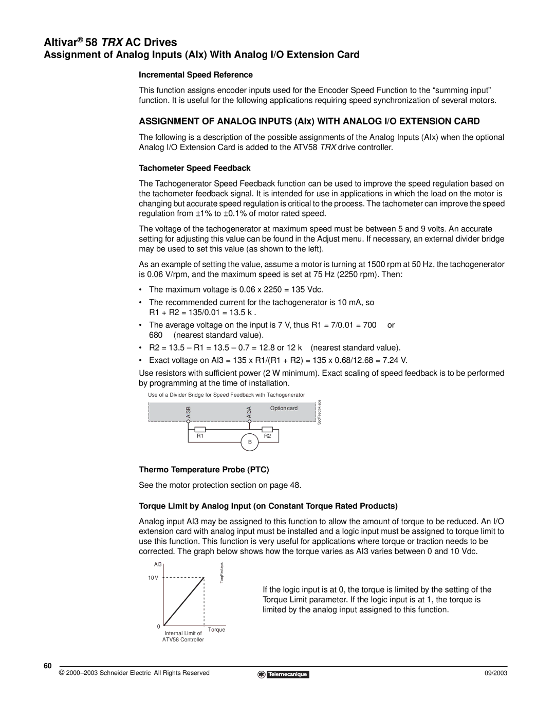
The voltage of the tachogenerator at maximum speed must be between 5 and 9 volts. An accurate setting for adjusting this value can be found in the Adjust menu. If necessary, an external divider bridge may be used to set this value (as shown to the left).
As an example of setting the value, assume a motor is turning at 1500 rpm at 50 Hz, the tachogenerator is 0.06 V/rpm, and the maximum speed is set at 75 Hz (2250 rpm). Then:
•The maximum voltage is 0.06 x 2250 = 135 Vdc.
•The recommended current for the tachogenerator is 10 mA, so R1 + R2 = 135/0.01 = 13.5 kΩ.
• | The average voltage on the input is 7 V, thus R1 = 7/0.01 = 700 Ω or |
| 680 Ω (nearest standard value). |
• | R2 = 13.5 – R1 = 13.5 – 0.7 = 12.8 or 12 kΩ (nearest standard value). |
• Exact voltage on AI3 = 135 x R1/(R1 + R2) = 135 x 0.68/12.68 = 7.24 V.
Use resistors with sufficient power (2 W minimum). Exact scaling of speed feedback is to be performed by programming at the time of installation.
Use of a Divider Bridge for Speed Feedback with Tachogenerator
AI3B | AI3A | Option card |
| ||
R1 | B | R2 |
|
|
SpdFeedbk.eps
Thermo Temperature Probe (PTC)
See the motor protection section on page 48.
Torque Limit by Analog Input (on Constant Torque Rated Products)
Analog input AI3 may be assigned to this function to allow the amount of torque to be reduced. An I/O extension card with analog input must be installed and a logic input must be assigned to torque limit to use this function. This function is very useful for applications where torque or traction needs to be corrected. The graph below shows how the torque varies as AI3 varies between 0 and 10 Vdc.
AI3
10 V
TorqRed.eps
If the logic input is at 0, the torque is limited by the setting of the Torque Limit parameter. If the logic input is at 1, the torque is limited by the analog input assigned to this function.
0
Torque
Internal Limit of
ATV58 Controller
60
© |
| 09/2003 |
| ||
|
|
|