|
|
|
|
|
|
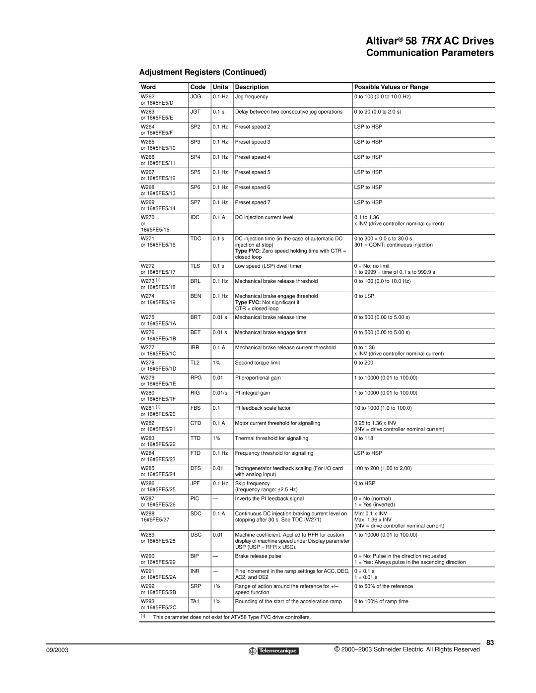
| Altivar® 58 TRX AC Drives | |
|
|
|
|
|
|
| Communication Parameters | |
| Adjustment Registers (Continued) |
|
| |||||
|
|
|
|
|
| |||
| Word | Code | Units | Description | Possible Values or Range | |||
|
|
|
|
|
| |||
| W262 | JOG | 0.1 Hz | Jog frequency | 0 to 100 (0.0 to 10.0 Hz) | |||
| or 16#5FE5/D |
|
|
|
|
|
|
|
|
|
|
|
|
| |||
| W263 | JGT | 0.1 s | Delay between two consecutive jog operations | 0 to 20 (0.0 to 2.0 s) | |||
| or 16#5FE5/E |
|
|
|
|
|
|
|
|
|
|
|
|
| |||
| W264 | SP2 | 0.1 Hz | Preset speed 2 | LSP to HSP | |||
| or 16#5FE5/F |
|
|
|
|
|
|
|
|
|
|
|
|
| |||
| W265 | SP3 | 0.1 Hz | Preset speed 3 | LSP to HSP | |||
| or 16#5FE5/10 |
|
|
|
|
|
|
|
|
|
|
|
|
| |||
| W266 | SP4 | 0.1 Hz | Preset speed 4 | LSP to HSP | |||
| or 16#5FE5/11 |
|
|
|
|
|
|
|
|
|
|
|
|
| |||
| W267 | SP5 | 0.1 Hz | Preset speed 5 | LSP to HSP | |||
| or 16#5FE5/12 |
|
|
|
|
|
|
|
|
|
|
|
|
| |||
| W268 | SP6 | 0.1 Hz | Preset speed 6 | LSP to HSP | |||
| or 16#5FE5/13 |
|
|
|
|
|
|
|
|
|
|
|
|
| |||
| W269 | SP7 | 0.1 Hz | Preset speed 7 | LSP to HSP | |||
| or 16#5FE5/14 |
|
|
|
|
|
|
|
|
|
|
|
|
| |||
| W270 | IDC | 0.1 A | DC injection current level | 0.1 to 1.36 | |||
| or |
|
|
|
|
| x INV (drive controller nominal current) | |
| 16#5FE5/15 |
|
|
|
|
|
|
|
|
|
|
|
|
| |||
| W271 | TDC | 0.1 s | DC injection time (in the case of automatic DC | 0 to 300 = 0.0 s to 30.0 s | |||
| or 16#5FE5/16 |
|
| injection at stop) | 301 = CONT: continuous injection | |||
|
|
|
| Type FVC: Zero speed holding time with CTR = |
|
| ||
|
|
|
| closed loop |
|
| ||
|
|
|
|
|
| |||
| W272 | TLS | 0.1 s | Low speed (LSP) dwell timer | 0 = No: no limit | |||
| or 16#5FE5/17 |
|
|
|
|
| 1 to 9999 = time of 0.1 s to 999.9 s | |
|
|
|
|
|
| |||
| W273 [1] | BRL | 0.1 Hz | Mechanical brake release threshold | 0 to 100 (0.0 to 10.0 Hz) | |||
| or 16#5FE5/18 |
|
|
|
|
|
|
|
|
|
|
|
|
| |||
| W274 | BEN | 0.1 Hz | Mechanical brake engage threshold | 0 to LSP | |||
| or 16#5FE5/19 |
|
| Type FVC: Not significant if |
|
| ||
|
|
|
| CTR = closed loop |
|
| ||
|
|
|
|
|
| |||
| W275 | BRT | 0.01 s | Mechanical brake release time | 0 to 500 (0.00 to 5.00 s) | |||
| or 16#5FE5/1A |
|
|
|
|
|
|
|
|
|
|
|
|
| |||
| W276 | BET | 0.01 s | Mechanical brake engage time | 0 to 500 (0.00 to 5.00 s) | |||
| or 16#5FE5/1B |
|
|
|
|
|
|
|
|
|
|
|
|
| |||
| W277 | IBR | 0.1 A | Mechanical brake release current threshold | 0 to 1.36 | |||
| or 16#5FE5/1C |
|
|
|
|
| x INV (drive controller nominal current) | |
|
|
|
|
|
| |||
| W278 | TL2 | 1% | Second torque limit | 0 to 200 | |||
| or 16#5FE5/1D |
|
|
|
|
|
|
|
|
|
|
|
|
| |||
| W279 | RPG | 0.01 | PI proportional gain | 1 to 10000 (0.01 to 100.00) | |||
| or 16#5FE5/1E |
|
|
|
|
|
|
|
|
|
|
|
|
| |||
| W280 | RIG | 0.01/s | PI integral gain | 1 to 10000 (0.01 to 100.00) | |||
| or 16#5FE5/1F |
|
|
|
|
|
|
|
|
|
|
|
|
| |||
| W281 [1] | FBS | 0.1 | PI feedback scale factor | 10 to 1000 (1.0 to 100.0) | |||
| or 16#5FE5/20 |
|
|
|
|
|
|
|
|
|
|
|
|
| |||
| W282 | CTD | 0.1 A | Motor current threshold for signalling | 0.25 to 1.36 x INV | |||
| or 16#5FE5/21 |
|
|
|
|
| (INV = drive controller nominal current) | |
|
|
|
|
|
| |||
| W283 | TTD | 1% | Thermal threshold for signalling | 0 to 118 | |||
| or 16#5FE5/22 |
|
|
|
|
|
|
|
|
|
|
|
|
| |||
| W284 | FTD | 0.1 Hz | Frequency threshold for signalling | LSP to HSP | |||
| or 16#5FE5/23 |
|
|
|
|
|
|
|
|
|
|
|
|
| |||
| W285 | DTS | 0.01 | Tachogenerator feedback scaling (For I/O card | 100 to 200 (1.00 to 2.00) | |||
| or 16#5FE5/24 |
|
| with analog input) |
|
| ||
|
|
|
|
|
| |||
| W286 | JPF | 0.1 Hz | Skip frequency | 0 to HSP | |||
| or 16#5FE5/25 |
|
| (frequency range: ±2.5 Hz) |
|
| ||
|
|
|
|
|
| |||
| W287 | PIC | — | Inverts the PI feedback signal | 0 = No (normal) | |||
| or 16#5FE5/26 |
|
|
|
|
| 1 = Yes (inverted) | |
|
|
|
|
|
| |||
| W288 | SDC | 0.1 A | Continuous DC injection braking current level on | Min: 0.1 x INV | |||
| 16#5FE5/27 |
|
| stopping after 30 s. See TDC (W271) | Max: 1.36 x INV | |||
|
|
|
|
|
|
| (INV = drive controller nominal current) | |
|
|
|
|
|
| |||
| W289 | USC | 0.01 | Machine coefficient. Applied to RFR for custom | 1 to 10000 (0.01 to 100.00) | |||
| or 16#5FE5/28 |
|
| display of machine speed under Display parameter |
|
| ||
|
|
|
| USP (USP = RFR x USC). |
|
| ||
|
|
|
|
|
| |||
| W290 | BIP | — | Brake release pulse | 0 = No: Pulse in the direction requested | |||
| or 16#5FE5/29 |
|
|
|
|
| 1 = Yes: Always pulse in the ascending direction | |
|
|
|
|
|
| |||
| W291 | INR | — | Fine increment in the ramp settings for ACC, DEC, | 0 = 0.1 s | |||
| or 16#5FE5/2A |
|
| AC2, and DE2 | 1 = 0.01 s | |||
|
|
|
|
|
| |||
| W292 | SRP | 1% | Range of action around the reference for +/– | 0 to 50% of the reference | |||
| or 16#5FE5/2B |
|
| speed function |
|
| ||
|
|
|
|
|
| |||
| W293 | TA1 | 1% | Rounding of the start of the acceleration ramp | 0 to 100% of ramp time | |||
| or 16#5FE5/2C |
|
|
|
|
|
|
|
|
|
|
|
|
|
| ||
| [1] This parameter does not exist for ATV58 Type FVC drive controllers. |
|
| |||||
|
|
|
|
|
|
|
| 83 |
09/2003 |
|
|
|
|
| © | ||
|
|
|
| |||||
|
|
|
|
|
|
|
|
|