Altivar® 58 TRX AC Drives
Assignment of Logic Inputs (LIx)
f | (Hz) |
|
|
|
|
| PlusMinusEx1.eps |
|
|
|
|
|
|
|
| ||
|
|
|
|
|
|
| t |
|
Forward | 1 |
|
|
|
|
|
|
|
or |
|
|
|
|
|
|
| |
|
|
|
|
|
| t |
| |
Reverse | 0 |
|
|
|
|
|
| |
|
|
|
|
|
|
| ||
+ Speed | 1 |
|
|
|
|
|
|
|
0 |
|
|
|
|
| t |
| |
|
|
|
|
|
|
| ||
|
|
|
|
|
|
|
| |
- Speed | 1 |
|
|
|
|
|
|
|
|
|
|
|
|
| t |
| |
| 0 |
|
|
|
|
|
| |
|
|
|
|
|
|
|
| |
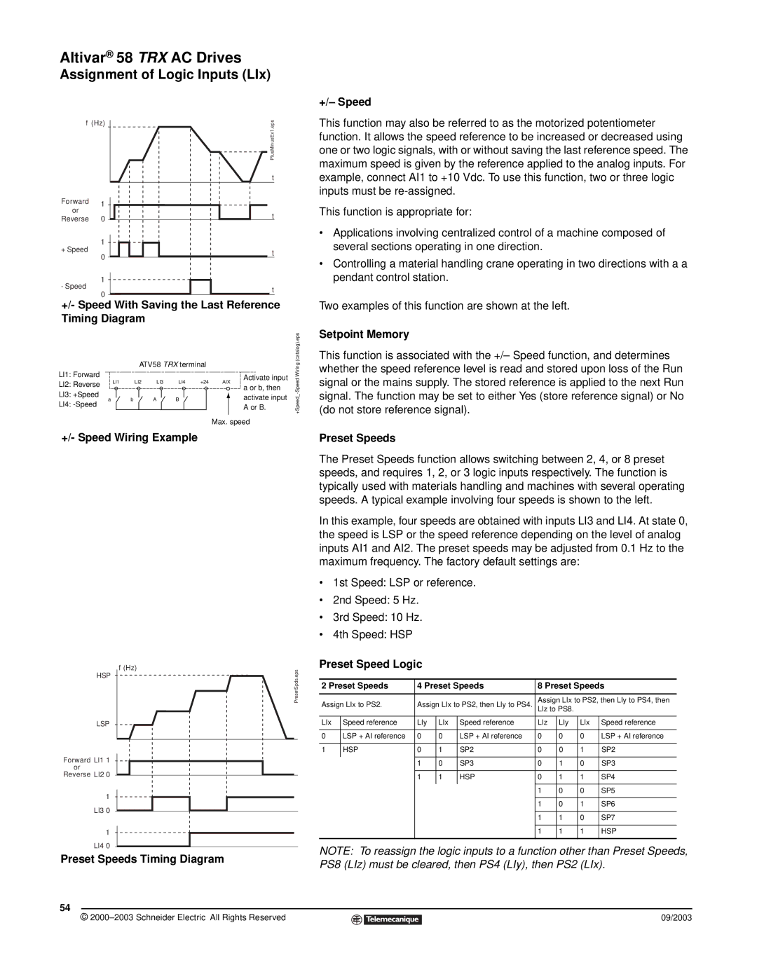
+/- Speed With Saving the Last Reference |
| |||||||
Timing Diagram |
|
|
|
|
| |||
|
|
| ATV58 TRX terminal |
|
| (catalog).eps | ||
|
|
|
|
| Wiring | |||
LI1: Forward |
|
|
|
|
| Activate input | ||
|
|
|
|
| Speed | |||
LI2: Reverse | LI1 | LI2 | LI3 | LI4 +24 |
| |||
| a or b, then | |||||||
|
| AIX |
| |||||
LI3: +Speed |
|
|
|
|
|
| - | |
LI4: | a | b | A | B |
| activate input | +Speed_ | |
| ||||||||
|
|
|
|
| A or B. | |||
|
|
|
|
|
|
|
| |
|
|
|
|
|
| Max. speed |
| |
+/- Speed Wiring Example
HSP | f (Hz) | PresetSpds.eps |
| ||
|
|
LSP
Forward LI1 1
or
Reverse LI2 0
1
LI3 0
1
LI4 0
Preset Speeds Timing Diagram
54
©
+/– Speed
This function may also be referred to as the motorized potentiometer function. It allows the speed reference to be increased or decreased using one or two logic signals, with or without saving the last reference speed. The maximum speed is given by the reference applied to the analog inputs. For example, connect AI1 to +10 Vdc. To use this function, two or three logic inputs must be
This function is appropriate for:
•Applications involving centralized control of a machine composed of several sections operating in one direction.
•Controlling a material handling crane operating in two directions with a a pendant control station.
Two examples of this function are shown at the left.
Setpoint Memory
This function is associated with the +/– Speed function, and determines whether the speed reference level is read and stored upon loss of the Run signal or the mains supply. The stored reference is applied to the next Run signal. The function may be set to either Yes (store reference signal) or No (do not store reference signal).
Preset Speeds
The Preset Speeds function allows switching between 2, 4, or 8 preset speeds, and requires 1, 2, or 3 logic inputs respectively. The function is typically used with materials handling and machines with several operating speeds. A typical example involving four speeds is shown to the left.
In this example, four speeds are obtained with inputs LI3 and LI4. At state 0, the speed is LSP or the speed reference depending on the level of analog inputs AI1 and AI2. The preset speeds may be adjusted from 0.1 Hz to the maximum frequency. The factory default settings are:
•1st Speed: LSP or reference.
•2nd Speed: 5 Hz.
•3rd Speed: 10 Hz.
•4th Speed: HSP
Preset Speed Logic
2 Preset Speeds | 4 Preset Speeds | 8 Preset Speeds | ||||||
|
|
|
|
|
| |||
Assign LIx to PS2. | Assign LIx to PS2, then LIy to PS4. | Assign LIx to PS2, then LIy to PS4, then | ||||||
LIz to PS8. |
|
| ||||||
|
|
|
|
|
|
|
|
|
LIx | Speed reference | LIy | LIx | Speed reference | LIz | LIy | LIx | Speed reference |
|
|
|
|
|
|
|
|
|
0 | LSP + AI reference | 0 | 0 | LSP + AI reference | 0 | 0 | 0 | LSP + AI reference |
|
|
|
|
|
|
|
|
|
1 | HSP | 0 | 1 | SP2 | 0 | 0 | 1 | SP2 |
|
|
|
|
|
|
|
|
|
|
| 1 | 0 | SP3 | 0 | 1 | 0 | SP3 |
|
|
|
|
|
|
|
|
|
|
| 1 | 1 | HSP | 0 | 1 | 1 | SP4 |
|
|
|
|
|
|
|
|
|
|
|
|
|
| 1 | 0 | 0 | SP5 |
|
|
|
|
|
|
|
|
|
|
|
|
|
| 1 | 0 | 1 | SP6 |
|
|
|
|
|
|
|
|
|
|
|
|
|
| 1 | 1 | 0 | SP7 |
|
|
|
|
|
|
|
|
|
|
|
|
|
| 1 | 1 | 1 | HSP |
|
|
|
|
|
|
|
|
|
NOTE: To reassign the logic inputs to a function other than Preset Speeds, PS8 (LIz) must be cleared, then PS4 (LIy), then PS2 (LIx).
09/2003